Thursday 30 May 2024

Basic of Gear, Belts, Stepper Motor Drive

 Gears:


Gears are mechanical devices used to transmit power and motion between two shafts. They consist of toothed wheels with interlocking teeth that mesh together. Gears are classified based on their shape and arrangement of teeth, including spur gears, helical gears, bevel gears, and worm gears.

  • Spur Gears: Spur gears are the most common type of gear, with teeth that are straight and parallel to the gear axis. They transmit power between parallel shafts and provide a constant speed ratio.

  • Helical Gears: Helical gears have teeth that are angled along the gear axis, resembling a helix. They provide smoother and quieter operation compared to spur gears but generate axial thrust.

  • Bevel Gears: Bevel gears have cone-shaped teeth and are used to transmit motion between intersecting shafts at right angles.

  • Worm Gears: Worm gears consist of a worm (a threaded shaft) and a worm wheel (a gear). They are used to transmit motion between perpendicular shafts, with high gear reduction ratios.

Gears are crucial components in various mechanical systems, including automobiles, machinery, and industrial equipment.

Belts:

Belts are flexible loops used to transmit power between two shafts that are not directly connected. They operate based on frictional forces between the belt and pulleys (wheels) connected to the shafts. Belts are commonly made of materials like rubber, neoprene, or polyurethane.


  • Types of Belts:
    • Flat Belts: Flat belts are simple, flat strips that wrap around pulleys to transmit power. They are used in applications with low power requirements.


    • V-Belts: V-belts have a trapezoidal cross-section and are used in applications requiring higher power transmission, offering better grip and efficiency compared to flat belts.
    • Timing Belts: Timing belts have teeth on their inner surface and are used in applications requiring precise synchronization of shaft rotation, such as in engines and robotics.

Belts are widely used in various industries for applications like driving conveyor systems, power transmission in machinery, and automotive engine timing systems.

Stepper Motor Drives:

Stepper motor drives are electronic devices used to control the operation of stepper motors, which are electromechanical devices that convert electrical pulses into precise mechanical motion. Stepper motors move in discrete steps, making them ideal for applications requiring precise positioning and control.

  • Types of Stepper Motor Drives:
    • Open-Loop Drives: Open-loop drives provide basic control of stepper motors without feedback on the motor's actual position. They are simpler and less expensive but may lack precision.
    • Closed-Loop Drives: Closed-loop drives use feedback mechanisms, such as encoders or sensors, to monitor the motor's position and provide accurate control and positioning.

Stepper motor drives are used in various applications, including 3D printers, CNC machines, robotics, and automated equipment, where precise motion control is required.

These components—gears, belts, and stepper motor drives—are essential elements in many mechanical and electromechanical systems, playing critical roles in transmitting power, motion, and control.

SIMM AND DIMM Memory Modules

 SIMM (Single In-Line Memory Module) and DIMM (Dual In-Line Memory Module) are two types of memory modules used in computers to provide Random Access Memory (RAM) for the system. Here's a comparison between SIMM and DIMM memory modules:

SIMM (Single In-Line Memory Module):

  1. Design: SIMMs have a single row of contacts on one side of the module. They are typically used in older computer systems.

  2. Memory Width: SIMMs are usually 32 bits wide for data, meaning they transfer data in 32-bit chunks.

  3. Capacity: SIMMs are available in various capacities, typically ranging from 1 MB to 256 MB (megabytes).

  4. Installation: SIMMs are installed in a single bank on the motherboard, often requiring two or more modules to be installed to achieve the desired amount of RAM.

  5. Parity: Some SIMMs feature parity memory, which includes an extra bit for error-checking purposes.

  6. Obsolete: SIMMs have become obsolete in modern computer systems and are rarely used in new builds or upgrades.


DIMM (Dual In-Line Memory Module):

  1. Design: DIMMs have two rows of contacts on both sides of the module, providing more pins for data transfer. They are the standard memory module used in modern computer systems.

  2. Memory Width: DIMMs are typically 64 bits wide for data, allowing for higher bandwidth compared to SIMMs.

  3. Capacity: DIMMs are available in higher capacities compared to SIMMs, ranging from a few hundred megabytes to several gigabytes.

  4. Installation: DIMMs are installed in separate memory slots on the motherboard, allowing for more flexibility in terms of configuration and upgrades. Most modern motherboards support dual-channel or quad-channel memory configurations with DIMMs.

  5. Types: DIMMs come in various types, including DDR (Double Data Rate), DDR2, DDR3, DDR4, and DDR5, each offering improvements in speed and efficiency over previous generations.

  6. ECC Support: Some DIMMs support Error-Correcting Code (ECC) memory, which can detect and correct errors in data stored in memory.

  7. Current Standard: DIMMs are the standard memory module used in modern PCs, laptops, servers, and workstations.

In summary, while SIMMs were prevalent in older computer systems, DIMMs have become the standard memory module used in modern computing due to their higher capacity, faster data transfer rates, and compatibility with current hardware standards.

Replacing the CMOS battery on a motherboard

Replacing the CMOS battery on a motherboard is a relatively straightforward process, but it's essential to handle it carefully to avoid damaging the motherboard or other components. Here's a step-by-step guide:


1. Gather Supplies:

  • A new CMOS battery (usually a CR2032 lithium coin cell battery).
  • Screwdriver (if necessary to access the battery compartment).

2. Power Off and Unplug:

  • Shut down your computer completely and unplug it from the power outlet to avoid electrical shock.

3. Open the Case:

  • Depending on your computer case, you may need to remove side panels or access panels to reach the motherboard. Use a screwdriver to remove any screws holding the panels in place.

4. Locate the Battery:

  • Look for the CMOS battery on the motherboard. It's typically a small, silver coin cell battery located near the CPU socket or PCIe slots. It may be held in place by a clip or a small plastic holder.

5. Remove the Old Battery:

  • Carefully push or slide the clip holding the battery, or use your fingers to gently pry the old battery out of its holder. Take note of the battery's orientation so you can install the new one correctly.

6. Install the New Battery:

  • Insert the new CMOS battery into the holder with the correct orientation (usually with the positive side facing up). Ensure that the battery is securely seated in its holder.

7. Close the Case:

  • Put the side panels or access panels back on the computer case and secure them with screws if necessary.

8. Power On and Test:

  • Plug in your computer and power it on. Check if the BIOS settings are retained properly, indicating that the new CMOS battery is working correctly.

9. Set BIOS Settings (If Necessary):

  • In some cases, replacing the CMOS battery may reset the BIOS settings to default. If this happens, you may need to enter the BIOS setup utility and configure the settings according to your preferences.

10. Dispose of the Old Battery Properly:

  • Dispose of the old CMOS battery safely according to local regulations for electronic waste disposal. Lithium batteries should not be thrown in the regular trash.

By following these steps, you can safely replace the CMOS battery on your motherboard and ensure that your computer's BIOS settings are retained properly.


MOTHERBOARD FORM FACTOR

Computer motherboard form factors refer to the standardized sizes and layouts of motherboards, which dictate their physical dimensions, mounting hole locations, and connector placements. Different form factors are designed to accommodate various case sizes, component configurations, and usage scenarios. Here are some common computer motherboard form factors:


  1. ATX (Advanced Technology eXtended): ATX is the most popular motherboard form factor for desktop PCs. It typically measures around 12" x 9.6" (305 mm x 244 mm) and provides ample space for expansion slots, RAM slots, and connectors. ATX motherboards are widely compatible with ATX cases and offer a good balance of features and expandability.

  2. MicroATX (mATX): MicroATX motherboards are smaller than ATX boards, typically measuring around 9.6" x 9.6" (244 mm x 244 mm). They offer fewer expansion slots and connectors compared to ATX, making them suitable for smaller cases or budget-oriented builds. MicroATX motherboards are compatible with both MicroATX and ATX cases.

  3. Mini-ITX: Mini-ITX is the smallest standard motherboard form factor, measuring around 6.7" x 6.7" (170 mm x 170 mm). Despite their compact size, Mini-ITX motherboards can accommodate a CPU socket, RAM slots, expansion slots (usually limited to one PCIe slot), and various connectors. Mini-ITX motherboards are popular for small form factor (SFF) and compact PC builds.

  4. Extended ATX (E-ATX): Extended ATX motherboards are larger than standard ATX boards, typically measuring over 12" in width. They offer additional expansion slots and connectors compared to ATX, making them suitable for high-end desktops or workstations with multiple GPUs, storage devices, and other peripherals. E-ATX motherboards may require compatible cases with extra space and mounting points.

  5. FlexATX: FlexATX is a compact motherboard form factor designed for space-constrained environments or specialized applications. It measures around 9" x 7.5" (229 mm x 191 mm) and offers limited expansion options compared to larger form factors. FlexATX motherboards are commonly used in small form factor PCs, embedded systems, or industrial applications.

  6. XL-ATX: XL-ATX is an extended version of the ATX form factor, offering additional space for more expansion slots and connectors. XL-ATX motherboards are larger than standard ATX and may require compatible cases with extra width to accommodate their size.

These are just a few examples of motherboard form factors, and there are others tailored for specific purposes or niche applications. When building a PC, it's important to ensure compatibility between the motherboard form factor, case size, and other components to create a balanced and functional system.

The primary differences between AT and ATX power supplies


The primary differences between AT and ATX power supplies lie in their design, form factor, and features. Here's a breakdown:

AT Power Supply:

  1. Design: AT (Advanced Technology) power supplies were the standard for PCs in the 1980s and early 1990s. They used a single 20-pin connector for the motherboard's power supply.

  2. Form Factor: AT power supplies are larger and less efficient compared to modern power supplies. They typically have a size of around 5.9" (width) x 3.4" (height) x 5.5" (depth).

  3. Switch: AT power supplies usually have a physical on/off switch directly on the power supply unit.

  4. Wiring: AT power supplies had fewer connectors and generally lower power output compared to modern power supplies.

ATX Power Supply:

  1. Design: ATX (Advanced Technology Extended) power supplies were introduced in the mid-1990s and became the standard for PCs. They use a 20 or 24-pin connector for the motherboard's power supply.

  2. Form Factor: ATX power supplies are more compact and efficient compared to AT power supplies. They adhere to specific form factors like ATX, microATX, and mini-ITX, with standardized dimensions.

  3. Switch: ATX power supplies typically do not have a physical on/off switch on the power supply unit itself. Instead, the power supply is controlled by the motherboard's power button.

  4. Wiring: ATX power supplies feature more connectors, including additional 4-pin or 8-pin CPU power connectors, SATA power connectors for modern hard drives and SSDs, PCIe power connectors for graphics cards, and more.

  5. Features: ATX power supplies often include features such as active power factor correction (PFC), which helps improve efficiency and reduce harmonic distortion.

  6. Compatibility: ATX power supplies are more compatible with modern motherboards and components, offering better support for newer technologies and higher power requirements.

In summary, ATX power supplies are more compact, efficient, and feature-rich compared to the older AT power supplies. They are the standard choice for modern PC builds due to their compatibility with current hardware and improved efficiency.

SMPS, Advantages And Disadvantages ,

 SMPS

"SMPS" typically stands for "Switched-Mode Power Supply." It's a type of power supply unit (PSU) that efficiently converts electrical power from one form to another using switching devices. SMPS is widely used in electronic devices because of its higher efficiency compared to traditional linear power supplies. It's commonly found in computers, TVs, LED lights, and other electronic appliances. What do you want to know about SMPS?


Certainly, here are some advantages and disadvantages of Switched-Mode Power Supplies (SMPS):

Advantages:

  1. Efficiency: SMPS is highly efficient compared to traditional linear power supplies. This efficiency means less energy is wasted as heat, resulting in lower power consumption and reduced operating costs.

  2. Size and Weight: SMPS are generally smaller and lighter than linear power supplies, making them ideal for applications where space and weight are critical factors.

  3. Regulated Output: SMPS can provide a stable and regulated output voltage even with fluctuations in input voltage or load conditions.

  4. Wide Input Voltage Range: SMPS can often operate over a wide range of input voltages, making them suitable for use with different power sources.

  5. Flexibility: SMPS can be designed to meet specific voltage and current requirements, making them versatile for a wide range of applications.

  6. Reduced Heat Dissipation: Due to their higher efficiency, SMPS generate less heat compared to linear power supplies, reducing the need for extensive cooling mechanisms.

Disadvantages:

  1. Complexity: SMPS circuits are more complex compared to linear power supplies, which can make their design, troubleshooting, and repair more challenging.

  2. Electromagnetic Interference (EMI): SMPS can produce electromagnetic interference that may affect other nearby electronic devices unless properly shielded.

  3. Voltage Spikes and Noise: SMPS can sometimes produce voltage spikes and electrical noise that may interfere with the performance of sensitive electronic equipment.

  4. Cost: While SMPS can be more efficient, smaller, and lighter, they often come with a higher initial cost compared to linear power supplies.

  5. Component Stress: SMPS components such as capacitors and inductors may experience higher stress levels due to the rapid switching frequencies involved, potentially leading to reduced lifespan if not properly designed.

  6. Compatibility Issues: Some SMPS designs may not be compatible with all types of loads, especially those with high inrush currents or reactive components.

Overall, while SMPS offer numerous advantages in terms of efficiency, size, and performance, they also come with certain drawbacks that need to be carefully considered during the design and implementation process.


Theory - 7 :-Different Types of Fuses and their Applications

Different Types of Fuses and their Applications

Different Types of Fuses

A fuse is probably the simplest electrical device, but its function is critical in protecting electrical circuits from damage. Fuses are found in every circuit in one form or another in various shapes, sizes, and ratings. In this article, we will learn how a fuse works and about the different types of the fuse.


What is a Fuse and How does a fuse work?

The primary job of a fuse is to break the circuit if a current higher than desired is drawn by the circuit, thus preventing damage due to short circuits.

The simplest kind of fuse consists of a resistive element, selected carefully for its melting point. The working principle of a fuse is as follows, when a current passes through this element, a small voltage drop (small enough so the circuit downstream won’t be affected) is created across the element, and some power is dissipated as heat. The temperature of the element thus increases. For normal currents, this temperature increase is not enough to melt the filament. However, if the current draw exceeds the rated current of the fuse, the melting point is quickly reached. The resistive element melts and the circuit is interrupted. The thickness and length of the resistive element determine the rated current.

Fuse elements are made of zinc, copper, silver, aluminium or other alloys to provide predictable trip currents. The element must not oxidize or corrode over time.

Symbol of a Fuse

The standard IEEE/ANSI symbols for the fuse is as follows:

 Fuse Symbol

However, the IEC fuse is slightly different:


Symbol of Fuse


Types if Fuse

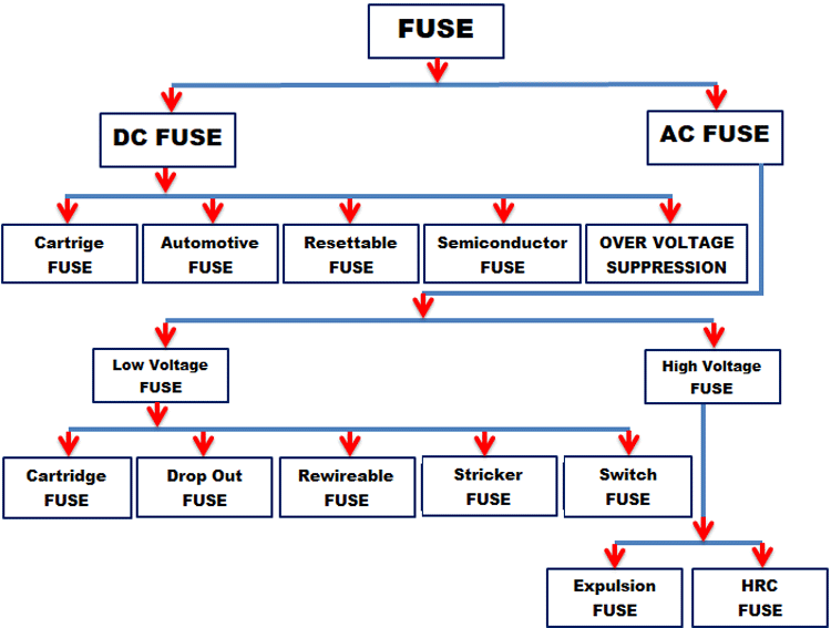
Fuses can be divided into two major categories, AC fuses, and DC fuses. The below block diagram illustrates the different types of the fuse under each category. We will discuss each fuse in brief in our article.

Types of Fuses

What is AC fuse and DC fuse?

As the name itself suggests, AC fuses are the ones we use in an AC circuit and the DC fuses are the ones we use in a DC circuit. The AC fuses are commonly rated for 120V or 240V depending on the grid voltage it is used with. they are designed to handle the alternating nature of the AC voltages. Like AC fuses, DC fuses are rated for particular voltage levels, but because DC voltage might be less forgiving than AC voltage, they must be more voltage-specific.

DC Fuses

1. CARTRIGE FUSES

CARTRIGE FUSES

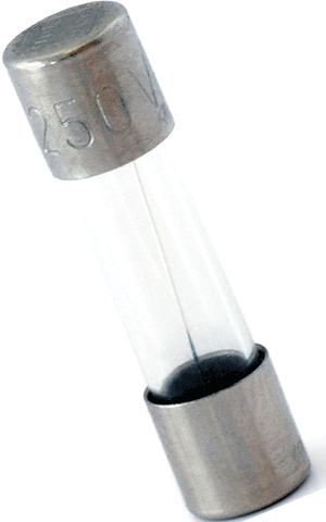
This is the most common type of fuse. They are also called glass fuse because the fuse element is encased in a glass envelope that is terminated by metal caps. The fuse element is encased in a glass envelope that is terminated by metal caps. The fuse is placed in an appropriate holder. Since the glass envelope is clear, it is easy to visually determine if the fuse is blown.

There are many variants of this design, including slow blow fuse and fast blow fuse. Slow blow fuses have a larger element that can handle overcurrent for a relatively short period of time and are unaffected by spikes in the appliance. Fast blow fuses react instantly to current spikes.

Some variants of this fuse are encased in ceramic to withstand high temperatures. Fuses for high voltage applications are filled with sand or oil. This is to prevent arcing between the two ends of the fuse after it has blown. SMD variants of cartridge fuses also exist for direct PCB mounting.

2. AUTOMOTIVE FUSES

Automotive Fuses

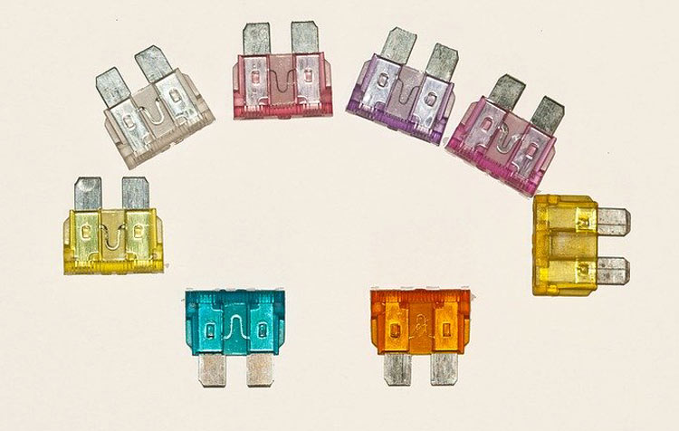
These fuses are specifically designed for automotive systems that run up to 32V and occasionally 42V. They are also called blade fuse because they come in ‘blade’ form (a transparent plastic envelope with flat contacts) and are colour-coded according to rated current. Some of these types are also used in other high-power circuits. The most common automotive refuse types are micro2, micro3, LP-min(APS), mini (ATM/APM), regular(APR / ATC / ATO / ATS) and maxi(APX). This classification is based on the physical dimensions of the fuse.

3. RESETTABLE FUSES/POLYFUSE 

Resettable Fuse

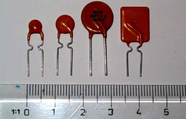
Like their name suggests, these fuses are self-resetting. They contain carbon black particles embedded in organic polymers. Normally, the carbon black makes the mixture conductive. When a large current flows, heat is generated which expands the organic polymer. The carbon black particles are forced apart, and conductivity decreases to the point where no current flows. Conductivity is restored as temperature decreases. Thus, the fuse does not have to be physically replaced. This kind of fuse is also called a PTC, meaning positive temperature coefficient, since resistance increases with temperature.

PTC Fuse is ubiquitous in computer power supplies and phone chargers. They are particularly handy here since replacement is difficult. For the same reason, they are used in aerospace devices.

PTCs are easily identified by their yellow-orange colour and disc (and occasionally rectangular) shape in their through-hole variants. SMD poly fuses usually come in green with white markings or black with gold markings. PTCs are available in virtually every current rating.

4. SEMICONDUCTOR FUSES 

The power dissipated by a semiconductor increases exponentially with current flow, and hence semiconductors are used for ultrafast fuses. These fuses are usually used to protect semiconductor switching devices that are sensitive to even small current spikes.

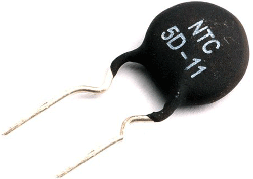
5. OVERVOLTAGE SUPPRESSION 

Sometimes voltage spikes can be harmful to circuits too, and often an overvoltage protection device is used with a fuse to protect against both voltage and current spikes.

NTCs (negative temperature coefficient) are placed in parallel with the supply. When the supply voltage spikes, NTC Fuses decrease resistance due to higher current flow and ‘absorb’ spikes.

NTC Fuses

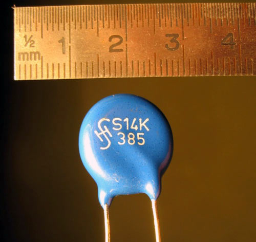
Metal oxide varistors (MOVs) are semiconductor like devices that bidirectionally absorb voltage spikes. You can learn more about MOV and its working using the linked article.

MOV Fuses

AC FUSES

HIGH VOLTAGE FUSES:

These fuses are used in high voltage AC transmission lines where voltages can exceed several hundreds of kilovolts. Some of the most popular high-voltage AC fuses are AJT125, ATQR4, TRS150R and AJT50.

HRC (High Rupture Current) fuses: HRC fuses are cartridge type fuses consisting of a transparent envelope made of steatite (magnesium silicate). The fuse is filled with quartz powder (and in the case of a liquid-filled HRC fuses, a non-conducting liquid like mineral oil) that acts as an arc extinguishing agent.

These fuses are used for very high fault currents.

High Rupture Current Fuses

Expulsion Fuses: These fuses are filled with chemicals like boric acid that produce gases on heating. These gases extinguish the arc and are expelled from the ends of the fuse. The fuse element is made of copper, tin or silver.
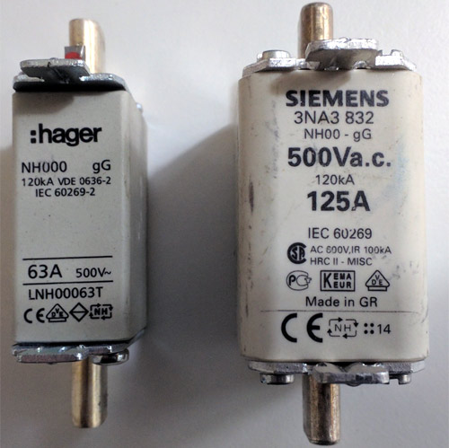
Expulsion Fuses

LOW VOLTAGE FUSES: 

These fuses are used in the relatively low voltage distribution networks.

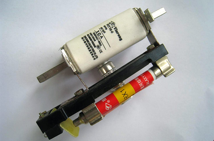
Cartridge fuses: They are very similar to cartridge DC fuses. They consist of a transparent envelope surrounding the fuse element. They can be plugged in (blade type) or screwed into a fixture (bolt type).

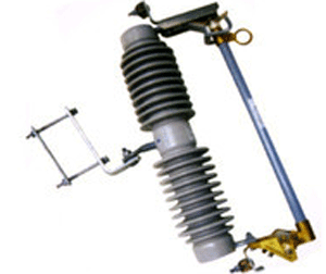
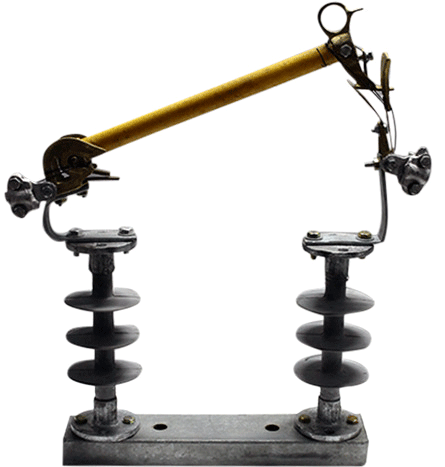
Drop out fuses: They contain a spring-loaded lever arm that retracts when a fault occurs and must be rewired and put back in place to resume normal operation. They are a type of expulsion fuse.

Drop Out Fuse

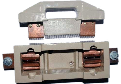
Rewireable fuses: They are a simple reusable fuse used in homes and offices. They consist of a carrier and a socket. When the fuse is blown, the carrier is taken out, rewired and put back in the socket to resume normal operation. They are somewhat less reliable than HRC fuses.

Rewireable Fuses

Striker fuse: These fuses are provided with a spring-loaded striker that can act as a visual indicator that the fuse has blown and also activate other switchgear.

Striker Fuses

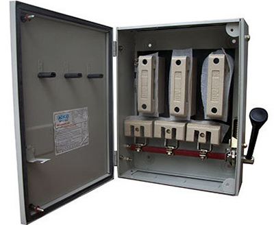
Switch fuse: A handle that is manually operated can connect or disconnect high current fuses.

Switch Fuses

Thoery-3.1 :- Artificial Respiration And Electrical Safety

 Artificial Respiration And Electrical Safety


Artificial respiration, also known as rescue breathing, is a life-saving technique used to manually provide oxygen to a person who is not breathing or is experiencing difficulty breathing. When it comes to artificial respiration and electrical safety, several precautions must be taken to ensure the safety of both the rescuer and the victim. Here are some key points:

  1. Assess the Scene: Before attempting artificial respiration, assess the scene for any electrical hazards. Ensure that the area is safe for both the rescuer and the victim.

  2. Ensure Electrical Safety: If the victim is in contact with electrical sources, do not approach them until the power is turned off and the area is safe. If you are unable to turn off the power, use a non-conductive object such as a wooden broom handle to move the victim away from the electrical source.

  3. Call for Help: If the victim is in contact with electricity, call emergency services immediately. Do not attempt to move the victim until the power is turned off, and professional help arrives.

  4. Check for Breathing: Assess the victim's breathing. If the victim is not breathing or is gasping for air, begin artificial respiration immediately.

  5. Positioning: Position the victim on their back on a flat surface. Tilt their head back slightly to open the airway.

  6. Create a Seal: Pinch the victim's nostrils closed with your fingers and place your mouth over their mouth to create a seal.

  7. Give Rescue Breaths: Give two rescue breaths, each lasting about one second, while watching for the chest to rise.

  8. Check for Pulse: After giving rescue breaths, check for a pulse. If there is no pulse, begin CPR.

  9. Monitor Vital Signs: Continue to monitor the victim's vital signs until professional help arrives.

  10. Remove from Electrical Source: If the victim is no longer in contact with electricity, carefully move them away from the electrical source to a safe location before administering artificial respiration.

  11. Avoid Metal Conductors: When performing artificial respiration, ensure that you and the victim are not in contact with metal conductors, as this could lead to electric shock.

  12. Training and Certification: Receive proper training and certification in CPR and artificial respiration techniques to ensure that you can respond effectively and safely in emergency situations involving electrical hazards.

By following these precautions and guidelines, you can perform artificial respiration safely in situations involving electrical hazards, potentially saving lives while minimizing the risk of injury to yourself and others.

Click To Lean More

Theory-4 :- Safety Signs

Safety signs play a crucial role in communicating important information and warnings to people in various environments, including workplaces, public spaces, and construction sites. Here are some common types of safety signs along with their meanings:


  1. Mandatory Signs:

    • These signs indicate actions that must be taken to comply with safety regulations.
    • Examples: "Wear Personal Protective Equipment (PPE)," "Keep Clear," "Emergency Exit," "No Smoking."

  2. Prohibition Signs:

    • Prohibition signs indicate actions or behaviors that are not allowed.
    • Examples: "No Entry," "No Smoking," "No Pedestrians," "No Unauthorized Personnel."

  3. Warning Signs:

    • Warning signs alert people to potential hazards or dangers in the vicinity.
    • Examples: "Caution: Wet Floor," "Warning: High Voltage," "Beware of Moving Machinery," "Hazardous Materials."

  4. Fire Safety Signs:

    • These signs provide information related to fire safety and emergency procedures.
    • Examples: "Fire Exit," "Fire Alarm Call Point," "Fire Extinguisher," "Assembly Point."

  5. Emergency Signs:

    • Emergency signs provide directions to emergency exits, equipment, or facilities.
    • Examples: "Emergency Exit," "First Aid Kit," "Emergency Shower," "Eye Wash Station."

  6. Safety Instruction Signs:

    • These signs provide instructions or information regarding safety procedures.
    • Examples: "Wash Your Hands," "Safety Glasses Required," "Do Not Touch," "Use Handrail."

  7. Construction Safety Signs:

    • Construction signs provide warnings and instructions specific to construction sites.
    • Examples: "Hard Hat Area," "Construction Zone Ahead," "Watch for Falling Objects," "Keep Out."


These safety signs are designed with standardized symbols and colors to ensure clear and consistent communication of hazards, prohibitions, instructions, and emergency procedures in various settings.

THoey -3 :- Types of injury at works place and how to prevent them

Workplaces can pose various risks to employees, leading to a range of injuries. Here are some common types of workplace injuries and preventive measures, accompanied by pictorial representations:

  1. Slips, Trips, and Falls:

    • Keep floors clean and dry.
    • Use non-slip mats in areas prone to wetness.
    • Ensure proper lighting and clear walkways.

  2. Musculoskeletal Injuries:

    • Use proper lifting techniques.
    • Provide ergonomic equipment and furniture.
    • Encourage regular breaks and stretching exercises.

  3. Struck by Objects:

    • Wear personal protective equipment (PPE) such as helmets and safety glasses.
    • Store materials properly and secure loose items.
    • Mark off areas where overhead work is being performed.

  4. Caught in or Between Objects:

    • Ensure machine guards are in place and functioning properly.
    • Use lockout/tagout procedures when servicing machinery.
    • Provide training on proper equipment operation and maintenance.

  5. Burns and Chemical Injuries:

    • Wear appropriate PPE such as gloves, goggles, and aprons.
    • Store chemicals in labeled containers and follow proper handling procedures.
    • Have emergency eyewash stations and fire extinguishers readily available.

  6. Repetitive Strain Injuries (RSI):

    • Implement job rotation to vary tasks and reduce repetitive motions.
    • Provide ergonomic workstations and tools.
    • Educate employees on RSI symptoms and encourage early reporting.

  7. Electrical Shocks:

    • Inspect electrical cords and equipment regularly for damage.
    • Use ground fault circuit interrupters (GFCIs) in wet or damp environments.
    • Provide training on electrical safety and proper use of equipment.

By implementing these preventive measures and providing visual aids like the pictorial representations above, workplaces can significantly reduce the risk of injuries and create a safer environment for employees.

Theory- 2 :- Moving and shifting heavy and delicate equipment

Moving and shifting heavy and delicate equipment requires careful planning and execution to ensure both the safety of the equipment and the individuals involved. Here are some steps to ensure safety:

  1. Assessment and Planning: Before moving any equipment, assess its weight, size, and fragility. Plan the move carefully, considering factors like pathways, door sizes, and any obstacles that might be in the way.

  2. Use Proper Equipment: Utilize appropriate tools and equipment such as dollies, carts, pallet jacks, or forklifts to move heavy items. Ensure that these tools are in good condition and rated for the weight of the equipment.

  3. Secure the Equipment: Secure the equipment properly onto the moving equipment using straps, ropes, or chains to prevent shifting during transport.

  4. Protective Gear: Wear appropriate personal protective equipment (PPE) such as steel-toed boots, gloves, and back support belts to prevent injuries.

  5. Team Communication: Establish clear communication among team members involved in the move. Use hand signals or radios to coordinate movements and ensure everyone is aware of their roles and responsibilities.

  6. Clear Pathways: Clear the pathways of any obstacles or hazards to ensure smooth movement of the equipment. Mark off the area to alert others of the ongoing move.

  7. Lift with Proper Technique: When lifting heavy equipment manually, use proper lifting techniques such as bending at the knees, keeping the back straight, and lifting with the legs rather than the back.

  8. Slow and Steady: Move the equipment slowly and steadily to maintain control and prevent accidents. Avoid sudden movements or jerks that could cause the equipment to shift or fall.

  9. Inspect the Destination: Before placing the equipment in its new location, inspect the area to ensure it can support the weight and is free from any hazards.

  10. Training: Ensure that all individuals involved in the move are properly trained in handling heavy equipment and understand safety procedures.

  11. Emergency Preparedness: Have a plan in place for dealing with emergencies such as equipment tipping or someone getting injured. Ensure that first aid supplies are readily available.

  12. Professional Assistance: For extremely heavy or delicate equipment, consider hiring professional movers who specialize in handling such items.

By following these safety precautions, you can minimize the risk of accidents and ensure a smooth and safe move for both the equipment and the individuals involved.

Popular Posts