Translate

Search This Blog

Information Technology

ICTSM: The Unseen Force Behind Seamless Operations.

Industrial Visit

Beyond the Classroom, into the Industry. Connecting Theory to the Real World, Where Skills Get Real.

The Blueprint for Success is in Your Hands.

Hands-on Training for a Head-Start Career.

Technology Made Simple

The Expertise to Uncomplicate Your World.

Where Minds and Machines Connect.

Transforming Ideas into Digital Reality.

Showing posts with label SEM- 01 Practical. Show all posts

Wednesday, 27 December 2023

EXPERIMENT - 43 : - Explain the construction and working of MOSFET.

What is a MOSFET? 


Metal oxide semiconductor field effect transistors (MOSFETs) are electrical devices that switch or amplify voltages in circuits

  • It has an insulated gate that has the ability to change its conductivity with the applied voltage that is further used for amplifying or switching electrical signals. 
  • It's a voltage-controlled device. 
  • Traditionally, the structure of a metal oxide semiconductor (MOS) is obtained by growing a layer of silicon dioxide on top of a silicon substrate by thermal oxidation and depositing a layer of metal or polycrystalline silicon.
  • A metal-insulator-semiconductor field-effect transistor (MISFET) and insulated-gate field-effect transistor (IGFET) are termed almost synonymous with MOSFET.

Generally, MOSFET is a four-terminal device.  MOSFET terminals are labeled as follows:

  • Source
  • Gate
  • Drain
  • Body

Frequently the body is connected to the source terminal, reducing the terminals to three.


Construction of MOSFET


The typical MOSFET circuit diagram is as follows:

  • The MOSFET's base is made up of p-type semiconductors.
  • Both forms of the base are heavily doped with an n-type impurity, denoted by the symbol n+ in the diagram.
  • The terminal's source and drain come from the strongly doped portions of the base.
  • For insulation, a layer of silicon dioxide is applied to the substrate layer.
  • On top of the silicon dioxide, a thin insulated metallic plate works as a capacitor.
  • The thin metallic plate is removed, revealing the gate terminal.
  • A voltage source is then connected between these two n-type areas to construct a DC circuit.

Working Principle of MOSFET


The main working principle of a MOSFET device is to be able to control the current flow and voltage between the drain and source terminals. It works almost like a switch. A MOSFET's operation is dependent upon the MOS capacitor. The MOS capacitor is the heart of the MOSFET.
  • The semiconductor surface which is located between the source and drain terminal below the oxide layer can be inverted from n-type to p-type by the application of either negative or positive gate voltages respectively.
  • The holes present beneath the oxide layer are pushed downward with the substrate when a repulsive force is applied for the positive gate voltage.
  • The depletion region is populated by bound negative charges associated with the acceptor atoms.
  • A channel is developed when electrons are reached. Electrons are also attracted to the positive voltage from the n+ source and drained into the channel by that voltage.
  • As a result, if a voltage is applied between the drain and source, current flows freely between them, and the gate voltage controls electron flow.
  • If we apply a negative voltage, a hole channel will be formed under the oxide layer, instead of the positive voltage.

Types of MOSFET


The flowchart below shows how MOSFETs are classified based on their structure and materials.


  • There are two types of MOSFETs: Enhancement and Depletion
  • Each class is available in either n-channel or p-channel configurations, resulting in a total of four MOSFET categories.

Depletion Mode

The Depletion mode P-N channel has the highest conductivity when there is no voltage at the gate terminal. The channel conductivity diminishes when the voltage across the gate terminal is either positive or negative.

Enhancement Mode

The circuit does not work if there is no voltage across the gate terminal. When the maximum voltage is applied across the gate terminal, the device's conductivity improves. The abbreviation NMOS is used to refer to N-channel MOSFETs and the P-channel MOSFETs are abbreviated as PMOS, and the circuit looks as follows:


Wednesday, 29 November 2023

Experiment-15 :- Study Of LCR Meter

LCR- The inductance (L), capacitance (C), and resistance (R) of an electrical component are measured using an LCR meter, a type of electronic test equipment. The phase difference between the current and voltage waveforms is also measured by LCR meter in addition to the ratio of the current and voltage RMS values. 

Basic measuring principles for LCR meter:

Impedance is a physical property that is measured using LCR meter, which are measuring equipment. The quantifier Z is used to express impedance, which is resistance to the passage of an AC current. It can be determined using the voltage V between the measurement target’s terminals and the current I flowing to it. Impedance is a vector that is expressed on a complex plane.

LCR meter’s front panel:

Control terminals on the LCR meter’s front panel.

1. ON/OFF Switch:

LCR meters power can be turned on or off using the ON/OFF switch. The main supply is connected with a LCR meter while the switch is in the ON position. When the LCR meters is turned ON, the indicator on the front panel will begin to illuminate.

2. Testing Terminals: The front panel’s two points are test terminals. To these test terminals is attached the component that will be measured.

3. Function Selector: The function selector is used to put the meter in the proper mode to measure a certain kind of component. The function selector should be set to R mode for resistance measurements, L mode for inductance measurements, and C mode for capacitance measurements if they are to be done simultaneously.

4. Range Selector: With the help of the range selector, components with high magnitude or low magnitude values can be measured with ease.

5. Scale: The final values of the measurement will be displayed on the LCR meter’s calibrated scale.

Construction of LCR Meter:

  • Wheatstone bridge and
  • RC ratio arm circuits

are important parts of the LCR meter. The component whose value needs to be determined is attached to one of the bridge’s arms.

For the various types of measures, there are different provisions.

DC Excitation: By stimulating the bridge with DC voltage, DC quantities will be measured.

AC Excitation: The Wheatstone bridge must be excited with an AC signal in order to conduct AC measurements. The oscillator is employed in the circuit to provide AC excitation. It produces a frequency of one kilohertz.

Working of LCR Meter:

To achieve full balance, the bridge is set at the null position. In addition to balancing the bridge, the meter’s sensitivity needs to be modified. In an emitter follower circuit, the bridge’s output is fed. An input to the detector amplifier is provided as the emitter follower circuit’s output.


                                                                               BRIDGE CONNECTION 

An input to the detector amplifier is provided as the emitter follower circuit’s output. A strong measuring signal of great magnitude is required in order to achieve the sustainable indication.

The attenuation factor causes the magnitude of the measured signal to decrease due to use of amplifier.

In order to obtain a DC output signal during AC excitation in a bridge, a rectifier is used.

Types of LCR Meter:

LCR Meter are 2 types,

  • Handheld LCR Meter and
  • Benchtop LCR Meter

Handheld LCR Meter:

The portability and small weight of handheld LCR meter are benefits. In this meter typically have an accuracy of +/-1%.


Benchtop LCR Meter:

Benchtop LCR meter typically come with more capabilities than handheld versions, including programmable frequencies, greater measurement accuracy down to 0.01%, computer control, and data collection for automated applications.


                                                        BENCHTOP LCR METER

Advantages of LCR Meter:

  • LCR meter offer quick output and accurate readings.
  • For accurate measurements LCR meter are used with test voltage and frequency.

Disadvantages of LCR Meter:

If the test voltage applied to the bridge of the LCR meter is high while excitation, the circuit will burn out. 

Application of LCR Meter:

  • The resistance, capacitance, and inductance of circuits and parts are measured at various frequencies using an LCR meter.
  • These instruments are utilized to test an impedance, a physical characteristic denoted by the quantifier “Z.”
  • Electrical engineers and various manufacturing industries frequently utilize this measurement instrument.


Experiment - 14 :-Identification of different types of inductors and its specifications.

 Theory:

An inductor (also choke, coil or reactor) is a passive two-terminal electrical component that stores energy in its magnetic field. For comparison, capacitor stores energy in an electric field and a resistor does not store energy but rather dissipates energy as heat. An inductor is usually made from a coil of conducting material, like copper wire, that is then wrapped around a core made from either air or a magnetic metal.

While a capacitor does not like changes in voltage, an inductor does not like changes in current.

Inductor is a device which can store energy in the form of magnetic field. Inductor opposes a sudden change in the flow of current. The function of an inductor is to provide opposition to a changing or varying current


Whenever a current change occurs within the coil windings, a voltage is induced across the ends of the coil. The polarity of the induced voltage is such that it opposes the current change occurring withinn the inductor. In more general terms, inductors are the opposite of capacitor, in that they are able to pass a dc current and block an ac current. The basic unit of inductance is the Henry (H). 

Mutual inductance: Inductor store energy in form of magnetic field. This field of an inductor extends outside of inductor & can be affected another inductor close by.


Which utilizes mutual inductance to alter voltage or current output is called transformer. Inductor that supplies current called as primary coil & inductor that picks up magnetic field is called secondary winding.


Types: 1. Fixed inductors: 

  • Air core inductor: It consist no. of turns of wire on ordinary cardboard former. Since there is air inside former. These are used in RF frequencies in turning coils. 

  • Iron core inductor: The coil wounded over solid or laminated iron core. 
This iron core is laminated pressed together but insulated from each other.
2. Variable inductors: 

They are used in tuning circuit for radio frequency. The winding is placed over a fiber or ceramic former & to change inductance, a ferrite core is employed. By changing position of screwed ferrite core inductance can be changed.


Conclusion: 


Experiment -13: - To Identify Different Types of Resistors From physical Appearance.


Aim: - To Identify Different Types of Resistors From physical Appearance.

Materials Required: - Various types of resistors, Measuring instruments Voltmeter, Ammeter, Ohm meter etc.

Theory:-

Resistance is the property of a material which opposes the flow of electric charges through it. The unit for measuring resistance is Ohms. It is measured using the Ohmmeter.

Resistors are components used in electrical and electronic circuits for making different voltages required for different electronic components.

There are two types of Resistors:-


The Ohm value (resistance) of these resistors is constant and cannot be altered. The examples are carbon resistors, Ceramic resistors and Wire wound resistors.

Different types of Variable resistors

These resistors, the ohm value can be varying. The examples are potentiometer, Preset, Fan regulator etc.


Experiment - 12:- Measure DC And AC Power Using Power Meter

 Current and Voltage Measurements with Multimeter 

 INTRODUCTION


1.1. Multimeter A multimeter is a measuring instrument that we will use frequently throughout electrical experiments. So it is better to learn how to use a multimeter. 

A Multimeter is an electronic instrument, every electronic technician and engineers widely used piece of test equipment. A multimeter is mainly used to measure the three basic electrical characteristics of voltage, current, and resistance. It can also be used to test continuity between two points in an electrical circuit. This post mainly introduces the basic information of multimeters, applications, and types of multimeters are in. Let’s see all of these. The multimeter has multi functionalities like, it acts like ammeter, voltmeter, and ohmmeter. It is a handheld device with positive and negative indicator needle over a numeric LCD digital display. Multimeters can be used for testing batteries, household wiring, electric motors, and power supplies.

1.1.1. Applications: The applications of ammeter mainly involve in various electrical and electronic projects for components testing and also used in different measurement applications in the multimeter. 

1 Temperature and Environmental Applications

  • Low-cost weather station 
  • DMM internal temperature 

2 Voltage Measurements 

  • High and low-value DC measurement
  • Peak to Peak and DC average measurement

3 Current Measurements

  • DC measurement
  • True RMS AC 

4 Resistance Measurement 

  • Micro ohmmeter 
  • Measuring resistance with constant voltage 
  • Measuring resistance with constant current 

5 Time and Frequency measurement 

  • Fast frequency 
  • Time measurement

 1.1.2. Types of Multimeters: 

There are different types of multimeters like Analog, Digital, and Fluke multimeters.

Digital Multimeter: We mostly used multimeter is a digital multimeter (DMM). The DMM performs all functions from AC to DC other than analog. It has two probes positive and negative indicated with black and red color is shown in the figure. The black probe connected to COM JACK and red probe connected by user requirement to measure ohm, volt, or amperes. The jack marked VΩ and the COM jack on the right of the picture are used for measuring voltages, resistance, and for testing a diode. The two jacks are utilized when an LCD that shows what is being measured (volts, ohms, amps, etc.). Overload protection prevents damage to the meter and the circuit and protects the user. 


The Digital Multimeter consists of an LCD, a knob to select various ranges of the three electrical characteristics, an internal circuitry consisting of a signal conditioning circuitry, an analog to digital converter. The PCB consists of concentric rings which are connected or disconnected based on the position of the knob. Thus as the required parameter and the range are selected, the section of the PCB is activated to perform the corresponding measurement. To measure the resistance, current flows from a constant current source through the unknown resistor and the voltage across the resistor are amplified and fed to an Analog to Digital Converter and the resultant output in form of resistance is displayed on the digital display. To measure an unknown AC voltage, the voltage is first attenuated to get the suitable range and then rectified to DC signal and the analog DC signal is fed to A/D converter to get the display, which indicates the RMS value of the AC signal. Similarly Figure 1.Digital multimeter to measure an AC or DC, the unknown input is first converted to a voltage signal and then fed to an analog to digital converter to get the desired output (with rectification in case of AC signal). 

II.APPARATUS

Resistance, cables, multimeter, basic electrical set. 

III. EXPERIMENTAL PROCEDURE 


1) Set up the circuit provided on the upside. 

2) If you have one multimeter, prepare it for 2 situations. You can use your multimeter for measuring current and voltage. 

3) Please make the connection of power supply. 

4) Do not forget that Ammeters are connected in series so that the current flows through them. The ideal ammeter has a resistance of zero. Voltmeters are connected in parallel to resistive elements in the circuit so that they measure the potential difference across (on each side of) the element. 

5) In this experiment, please fill the Table 1 for this circuit. 


Friday, 20 October 2023

Practical - 7 :- Measure the voltages of the given cells/battery using analog/digital multimeter

Measure the voltages of the given cells/battery using analog/digital multimeter 

Objectives: At the end of this exercise you shall be able to

  • Measure the voltage of given cell/battery using analog multimeter 
  • Measure the voltage of given cell/battery using digital multimeter.

Requirements Tools/Equipment's/Instruments

  • Digital multi meter with probes - 1 No
  • Analog multi meter with probes- 1 No

Materials/Components

  • Lead acid battery 6V/12V any AH rating  - 1 No
  • 1.5V/3V/9V battery -1 No each
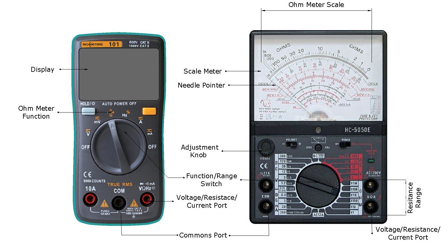
Digital-and-Analog-Multimeter-Parts

PROCEDURE 

TASK 1 : Measurement of cell/battery voltage using analog multimeter

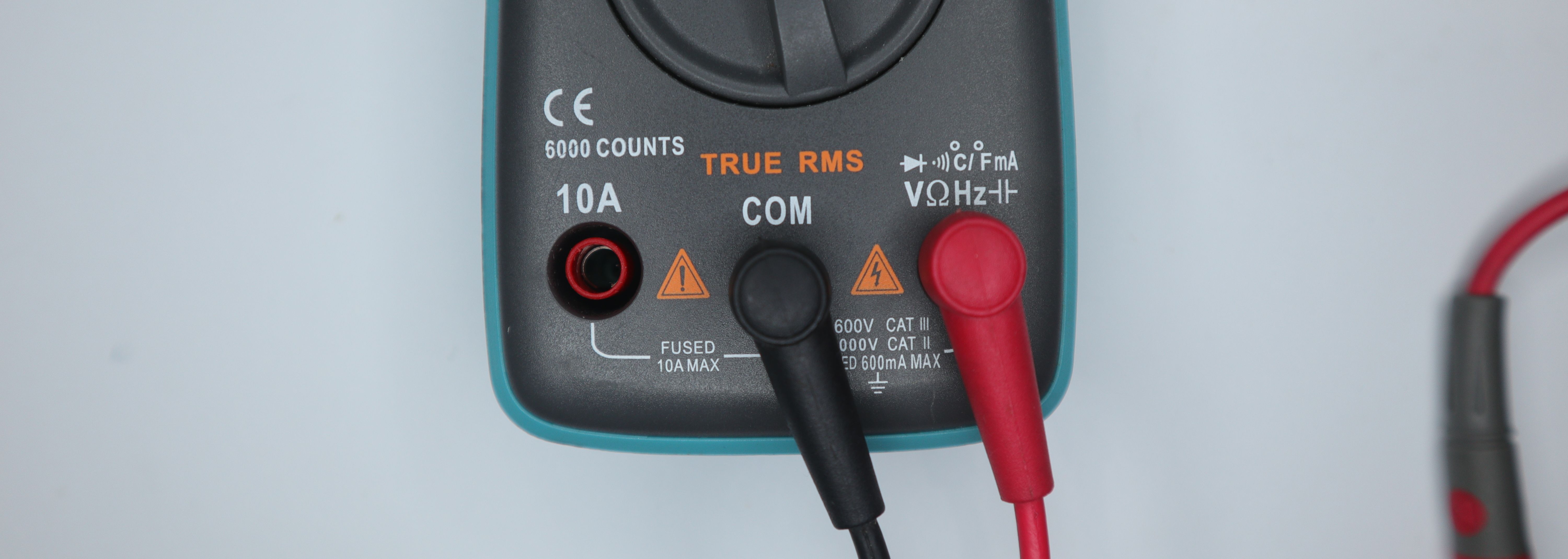
  1. Observe the front panel and insert the black colour probe “COM” socket of analog multimeter and insert the red colour probe into the V mA : socket as shown in Fig 1
    Multimeter ports
  2. Set the range selector knob of multimeter to DCV, as shown in Fig 2. 
    Multimeter functions switch
  3. Set the voltage range nearest to the cell / battery voltage as shown in Fig 3.
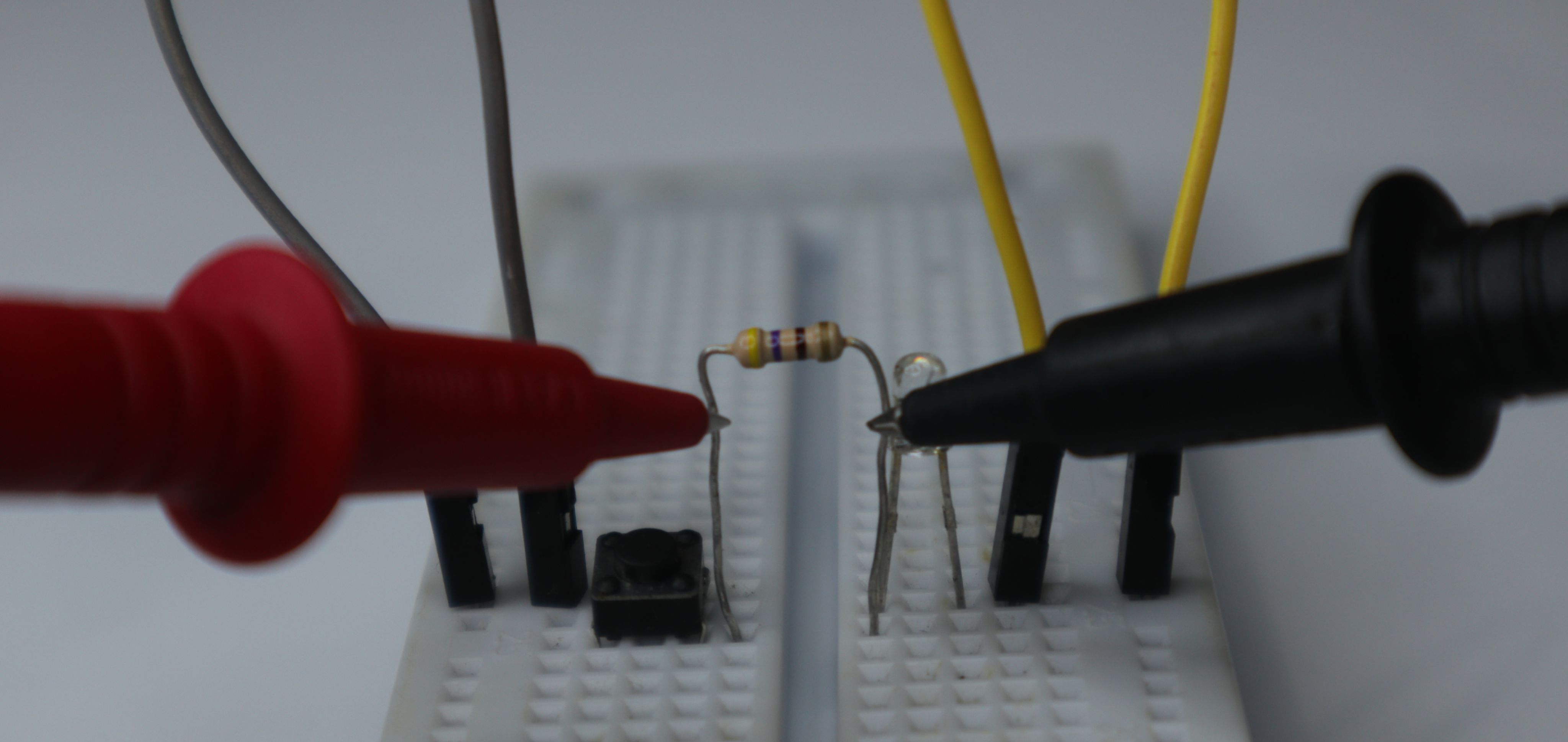
    Measuring resistance with multimeter probes
  4. Pick the 9V battery, place the black probe on the negative (-) terminal and red probe on the positive (+) terminal of the battery as shown in Fig 4.
  5. Check the Analog voltmeter reading as shown in Fig 5 and record the reading in Table 1. 6 Repeat step 4 and 5 for the remaining labelled cells/ battery. 7 Get the work checked by the Instructor

Experiment No. 8 Resistor Color Code and Measurement of Resistance

 Experiment No. 6 Resistor Color Code and Measurement of Resistance

 1. Introduction

 Objective: The aim of this experiment is to learn how to use the multimeter and how to calculate the                       value of the resistor.

 Components:

  •  Set of Resistors;
  • Multimeter.

1.3 Theory

1.3.1. Resistor: A passive electrical component with two terminals that are used for either limiting or regulating the flow of electric current in electrical circuits. The main purpose of resistor is to reduce the current flow and to lower the voltage in any particular portion of the circuit. It is made of copper wires which are coiled around a ceramic rod and the outer part of the resistor is coated with an insulating paint. 


Tolerance: Tolerance indicates how much the measured value of its actual resistance is different from its theoretical value, and it is calculated using percentages.

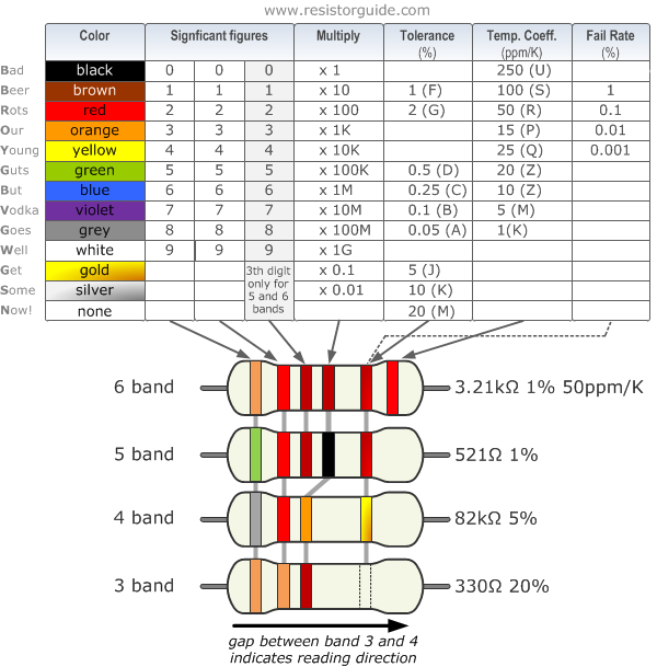
Resistor Color Code Chart

The chart below shows how to determine the resistance and tolerance for resistors. The table can also be used to specify the color of the bands when the values are known. An automatic resistor calculator can be used to quickly find the resistor values.

resistor color code chart

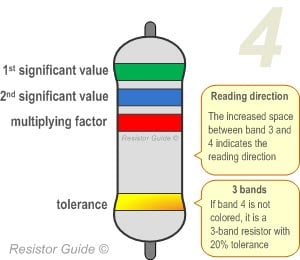
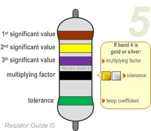
How to Read Resistor Colour Code?


four band resistor color code


  1. To read them, hold the resistor such that the tolerance band is on your right. The tolerance band is usually gold or silver in colour and is placed a little further away from the other bands.
  2.  Starting from your left, note down all the colours of the bands and write them down in sequence. 
  3.  Next, use the table given below to see which digits they represent.


    five band resistor color code

  4. The band just next to the tolerance band is the multiplier band. So if the colour of this band is Red (representing 2), the value given is 102 .

Experiment - 09 :- Desoldering Components from PCB using Desoldering pump

Objectives : At the end of this exercise you shall be able to 

• desoldering components from PCB using desoldering pump 

• desoldering component using desoldering wick. Requirements Tools/Equipments/Instruments 

• Trainees tool kit 

- 1 Set • Soldering iron, 25W 

-1 No • Desoldering pump (plunger type)

 - 1 No • Heat sink plier - 1 No

 Materials/Components 

• Desoldering wick - as reqd

 • Cleaning solution (IPA) - as reqd

 • Flux - as reqd

 • Cleaning Brush - 1 No

 • Safety goggles

 - 1 No • Crocodile clip

 - 1 No • Assembled PCB board for Desoldering work - as reqd

DESOLDERING

From using desoldering irons to sketchily knocking breadboard components off on the side of a table, there are tons of ways to remove components from a circuit board. Desoldering is an important skill to learn once you've gotten the hang of soldering, because messing up a soldering job isn't improbable.

  • This process is the removal of solder and components from a circuit board for troubleshooting, repair, replacement, and salvage.
  • It is the reverse process of soldering.
  • It is a process of removal of solder and components mounted on circuit boards.
  • The soldered joint is removed by the process of desoldering. For this purpose a small vacuum pump is used to remove solder from the plated through holes.
  • The lead over which the desoldering tip was placed is moved in a circular motion for rounded leads and back and forth for flat leads

Desoldering Basics

Materials Needed for Desoldering

a. Solder Sucker/ Desoldering Pump


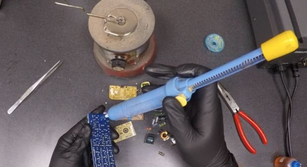
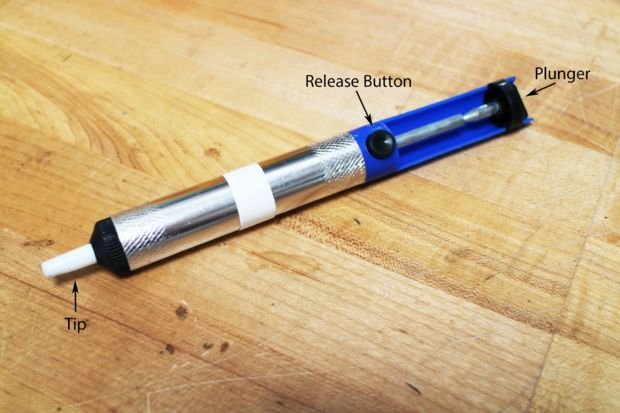
The most commonly used and convenient equipment needed for desoldering is the desoldering pump. A good manual solder sucker like this one works pretty well for selectively removing through holes parts from a PCB. Cheaper and smaller units do not work as well. They're marketed as compact but they don't works as well due to the limited stroke length and smaller cylinders.

Desoldering Process

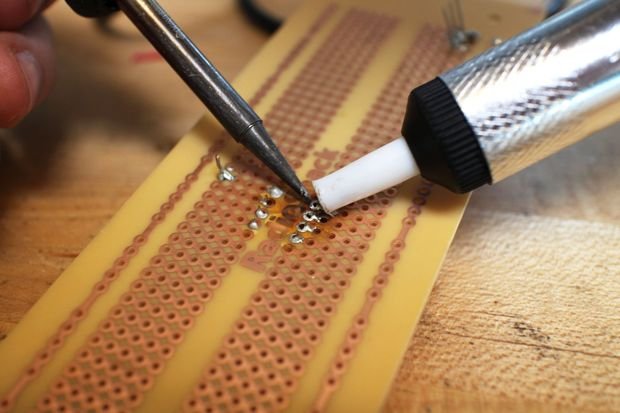
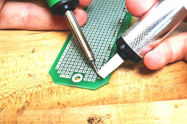
One of the nicest ways to desolder a component involves using a desoldering pump. A desoldering pump is essentially a small, high pressure vacuum. After heating up the solder, you can use the desoldering pump to suck the solder up and out of the way. Here are the basic steps for using a hand-powered desoldering pump:

1. Heat up the solder you want to remove with a soldering iron (some desoldering pumps also come with attached irons).
2. Press down on the plunger (If your pump has a bulb, just squeeze the bulb).
3. Once the solder is molten, place the tip of the desoldering pump against the solder that you want to remove.

4. Release the plunger or bulb. Some desoldering pumps have a release button so that you don't have to hold it the whole time.

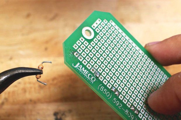
5. Remove free component.
6. Repeat steps 1-4 to remove any excess solder.
7. Dispose of the solder inside the pump by repeatedly pressing down and releasing the plunger.