Friday 31 March 2023

Practical -70:- Setup and configure a Virtual LAN.


Aim:

To construct a VLAN and make the PC’s communicate among a VLAN

Requirements

Windows pc – 6 Nos

CISCO Packet Tracer Software (Student Version)

8 port switch – 1 No

Cat-5 LAN cable

Procedure

Open the CISCO Packet tracer software

Drag and drop 6 pcs using End Device Icons on the left corner

Select 8 port switch from switch icon list in the left bottom corner

Make the connections using Straight through Ethernet cables

Give IP address of the PCs as per table, ping between PCs and observe the transfer of data packets in real and simulation mode.

Theory

A VLAN is a group of devices on one or more LANs that are configured to communicate as if they were attached to the same wire, when in fact they are located on a number of different LAN segments. Because VLANs are based on logical instead of physical connections, they are extremely flexible.

VLANs define broadcast domains in a Layer 2 network. A broadcast domain is the set of all devices that will receive broadcast frames originating from any device within the set. Broadcast domains are typically bounded by routers because routers do not forward broadcast frames. Layer 2 switches create broadcast domains based on the configuration of the switch. Switches are multiport bridges that allow you to create multiple broadcast domains. Each broadcast domain is like a distinct virtual bridge within a switch.


CONFIGURATION OF THE SWITCHPORT FOR VLAN:

Switch>en

Switch#config

Configuring from terminal, memory, or network [terminal]?

Enter configuration commands, one per line. End with CNTL/Z.

Switch(config)#vlan 10

Switch(config-vlan)#ex

Switch(config)#vlan 20

Switch(config-vlan)#ex

Switch(config)#interface range fastEthernet 0/1-3

Switch(config-if-range)#switchport access vlan 10

Switch(config-if-range)#ex

Switch(config)#interface range fastEthernet 0/4-6

Switch(config-if-range)#switchport access vlan 20

Switch(config-if-range)#ex

Switch(config)#ex

Switch#

%SYS-5-CONFIG_I: Configured from console by console


VLAN OUTPUT: (PINGING FROM PC0)


C:\>PING 10.0.0.2


Pinging 10.0.0.2 with 32 bytes of data:

Reply from 10.0.0.2: bytes=32 time=1ms TTL=128

Reply from 10.0.0.2: bytes=32 time<1ms TTL=128

Reply from 10.0.0.2: bytes=32 time<1ms TTL=128

Reply from 10.0.0.2: bytes=32 time<1ms TTL=128

Ping statistics for 10.0.0.2:


Packets: Sent = 4, Received = 4, Lost = 0 (0% loss),

Approximate round trip times in milli-seconds:

Minimum = 0ms, Maximum = 1ms, Average = 0ms


C:\>PING 20.0.0.1


Pinging 20.0.0.1 with 32 bytes of data:


Request timed out.

Request timed out.

Request timed out.

Request timed out.


Ping statistics for 20.0.0.1:

Packets: Sent = 4, Received = 0, Lost = 4 (100% loss),


Wednesday 29 March 2023

Practical-69 :- Practice TCP/IP Utilities : PING, IP CONFING, HOSTNAME, ROUTE, TRACERT Etc.


Tracert

This command is used to diagnose path-related problems. On an IP network, routers exchange IP packets between the source and the destination. They take IP packets from the source host and forward them in a sequence until they reach the destination host. The sequence of routers between the source and destination is known as the path. A path consists of all routers in a sequence that IP packets sent from the source host traverse to reach the destination host.

The tracert command prints the path. If all routers on the path are functional, this command prints the full path. If a router is down on the path, this command prints the path up to the last operational router.


Theory-74:-TCP /IP /FTP /Telnet

Protocols:

A protocol is a set of rules and guidelines for communicating data. A protocol is a standard used to define a method of exchanging data over a computer network such as local area network, Internet, Intranet, etc. Each protocol has its own method of how data is formatted when sent and what to do with it once received, how that data is compressed or how to check for errors in data.


Network protocols serve these basic functions:

  • Address data to the correct recipient(s)
  • Physically transmit data from source to destination, with security protection if needed
  • Receive messages and send responses appropriately.


TCP/IP:

Short for Transmission Control Protocol/Internet Protocol, TCP/IP is a set of rules (protocols) governing communications among all computers on the Internet. More specifically, TCP/IP dictates how information should be packaged (turned into bundles of information called packets), sent, and received, as well as how to get to its destination. TCP/IP was developed in 1978.

How does TCP/IP work?

As the name implies, TCP/IP is a combination of two separate protocols: Transmission Control Protocol (TCP) and Internet Protocol (IP). The Internet Protocol standard dictates the logistics of packets sent out over networks; it tells packets where to go and how to get there. IP has a method that lets any computer on the Internet forward a packet to another computer that is one or more intervals closer to the packet's recipient. You can think of it like workers in a line passing boulders from a quarry to a mining cart. The Transmission Control Protocol is responsible for ensuring the reliable transmission of data across Internet-connected networks. TCP checks packets for errors and submits requests for re-transmissions if any are found.

(FTP)File Transfer Protocol:

File Transfer Protocol (FTP) is a client/server protocol used for transferring files to or exchanging files with a host computer. It may be authenticated with user names and passwords. Anonymous FTP allows users to access files, programs and other data from the Internet without the need for a user ID or password. Web sites are sometimes designed to allow users to use 'anonymous' or 'guest' as a user ID and an email address for a password. What File Transfer Protocol can do:

  • Transfer files between computers.
  •  Create directories.
  •  Remove directories.
  •  List files.


Telnet :

Telnet (short for TErminal NETwork) is a network protocol used to provide a command line interface for communicating with a device.

Telnet is used most often for remote management but also sometimes for the initial setup for some devices, especially network hardware like switches, access points, etc. Managing files on a website is also something Telnet is sometimes used for. Telnet is sometimes written in uppercase as TELNET and may also be misspelled as Telenet.


The Telnet Protocol:

The Telnet protocol is designed to provide a bi-directional, eight-bit byte oriented communications facility to allow for aa standard method of interfacing terminal devices and processes.


  • Telnet is not the same thing as other TCP/IP protocols like HTTP, which just let you transfer files to and from a server. Instead, the Telnet protocol has you log on to a server as if you were an actual user, granting you direct control and all the same rights to files and applications as the user that you're logged in as.


Theory-73:-IP ROUTING IN NETWORK: RIP , IGRP


IP ROUTING IN NETWORK: RIP , IGRP

Introduction:

  • IP Routing is an umbrella term for the set of protocols that determine the path that data follows in order to travel across multiple networks from its source to its destination.
  • IP routing is the process of sending packets from a host on one network to another host on another, remote network. This process is done by routers.
  • Routers examine the destination IP address of a packet , determine the next-hop address, and forward the packet.
  • Routers use routing tables to determine a next hop address to which the packet should be forwarded.

IP Routing Process:

  • When an IP packet is to be forwarded, a router uses its forwarding table to determine the next hop for the packet's destination (based on the destination IP address in the IP packet header), and forwards the packet appropriately.
  • The next router then repeats this process using its own forwarding table, and so on until the packet reaches its destination. At each stage, the IP address in the packet header is sufficient information to determine the next hop; no additional protocol headers are required.
  • There are many types of routing protocols.
  • Routing Information Protocols(RIP)
  • Interior Gateway Protocol (IGRP)
  • Open Shortest Path First (OSPF)
  • Exterior Gateway Protocol (EGP)
  • Enhanced interior gateway routing protocol (EIGRP)
  • Border Gateway Protocol (BGP)
  • Intermediate System-to-Intermediate System (IS-IS

RIP (Routing Information Protocol):

  • RIP (Routing Information Protocol) is a forceful protocol type used in local area network and wide area network.
  • RIP (Routing Information Protocol) type is categorized interior gateway protocol within the use of distance vector algorithm.
  • RIP (Routing Information Protocol) is one of the oldest distance vector routing protocols. It is usually used in small networks.
  • RIP is very simple to configure and maintain, but lacks some advanced features of routing protocols like OSPF or EIGRP.
  • Two versions of the protocol exists: version 1 and version 2. Both versions use hop count as a metric and have the administrative distance of 120.
  • RIP version 2 is capable of advertising subnet masks and uses multicast to send routing updates, while version 1 doesn’t advertises subnet masks and uses broadcast for updates. Version 2 is backwards compatible with version 1.
  • RIPv2 sends the entire routing table every 30 seconds, which can consume a lot of bandwidth. RIPv2 uses multicast address of 224.0.0.9 to send routing updates, supports authentication and triggered updates (updates that are sent when a change in the network occurs). 

For example of how RIP works, consider the following figure.


  • Router R1 directly connects to the subnet 10.0.0.0/24. Network engineer has configured RIP on R1 to advertise this route. R1 sends routing updates to R2 and R3. The routing updates list the subnet, subnet mask and metric for this route. Each router, R2 and R3, receives this update and adds the route to their respective routing tables. Both routers list the metric of 1 because the network is only one hop away.
  • TIP – maximum hop count for a RIP route is 15. Any route with a higher hop count is considered to be unreachable.

Interior Gateway Routing Protocol (IGRP)

  • It is distance vector IGRP (Interior gateway Protocol) make-believe by Cisco.
  • Router used it to exchange routing data within an independent system.
  • Interior gateway routing protocol created in part to defeat the confines of RIP (Routing Information Protocol) in large networks.
  • It maintains multiple metrics for each route as well as reliability, MTU, delay load, and bandwidth.
  • The maximum hop of EIGRP is 255 and routing updates are transmitting 90 seconds. It measured in classful routing protocol, but it is less popular because of wasteful of IP address space.


Tuesday 28 March 2023

Theory-72 :- Transceivers (Media Converters)


Transceivers (Media Converters)


The term transceiver does describe a separate network device, but it can also be technology built and embedded in devices such as network cards and modems. In a network environment, a transceiver gets its name from being both a transmitter and a receiver of signals—thus the name transceivers.  Technically, on a LAN, the transceiver is responsible for placing signals onto the network media and also detecting incoming signals traveling through the same wire. Given the description of the function of a transceiver, it makes sense that that technology would be found with network cards.


Although transceivers are found in network cards, they can be external devices as well. As far as networking is concerned, transceivers can ship as a module or chip type. Chip transceivers are small and are inserted into a system board or wired directly on a circuit board. Module transceivers are external to the network and are installed and function similarly to other computer peripherals, or they can function as standalone devices.

There are many types of transceivers—RF transceivers, fiber optic transceivers, Ethernet transceivers, wireless (WAP) transceivers, and more. Though each of these media types is different, the function of the transceiver remains the same. Each type of the transceiver used has different characteristics, such as the number of ports available to connect to the network and whether full-duplex communication is supported.

Listed with transceivers in the CompTIA objectives are media converters. Media converters are a technology that allows administrators to interconnect different media types—for example, twisted pair, fiber, and Thin or thick coax—within an existing network. Using a media converter, it is possible to connect newer 100Mbps, Gigabit Ethernet, or ATM equipment to existing networks such as 10BASE-T or 100BASE-T. They can also be used in pairs to insert a fiber segment into copper networks to increase cabling distances and enhance immunity to electromagnetic interference (EMI).


Network Cards

Network cards, also called Network Interface Cards, are devices that enable computers to connect to the network.

When specifying or installing a NIC, you must consider the following issues:


  • System bus compatibility—If the network interface you are installing is an internal device, bus compatibility must be verified. The most common bus system in use is the Peripheral Component Interconnect (PCI) bus, but some older systems might still use Industry Standard Architecture (ISA) expansion cards.
  • System resources—Network cards, like other devices, need IRQ and memory I/O addresses. If the network card does not operate correctly after installation, there might be a device conflict.
  • Media compatibility—Today, the assumption is that networks use twisted-pair cabling, so if you need a card for coaxial or fiber-optic connections, you must specify this. Wireless network cards are also available.

Even more than the assumption you are using twisted-pair cabling is that the networking system being used is Ethernet. If you require a card for another networking system such as Token Ring, this must be specified when you order.


To install or configure a network interface, you will need drivers of the device, and might need to configure it, although many devices are now plug and play. Most network cards are now software configured. Many of these software configuration utilities also include testing capabilities. The drivers and software configuration utilities supplied with the cards are often not the latest available, so it is best practice to log on to the Internet and download the latest drivers and associated software.


Wireless Access Points


Wireless access points (APs) are a transmitter and receiver (transceiver) device used to create a wireless LAN (WLAN). APs are typically a separate network device with a built-in antenna, transmitter, and adapter. APs use the wireless infrastructure network mode to provide a connection point between WLANs and a wired Ethernet LAN. APs also typically have several ports allowing a way to expand the network to support additional clients.


Depending on the size of the network, one or more APs might be required. Additional APs are used to allow access to more wireless clients and to expand the range of the wireless network. Each AP is limited by a transmissions range—the distance a client can be from a AP and still get a useable signal. The actual distance depends on the wireless standard being used and the obstructions and environmental conditions between the client and the AP. Saying that an AP is used to extend a wired LAN to wireless clients doesn’t give you the complete picture. A wireless AP today can provide different services in addition to just an access point. Today, the APs might provide many ports that can be used to easily increase the size of the network. Systems can be added and removed from the network with no affect on other systems on the network. Also, many APs provide firewall capabilities and DHCP service. When they are hooked up, they will provide client systems with a private IP address and then prevent Internet traffic from accessing client systems. So in effect, the AP is a switch, a DHCP Server, router, and a firewall.

APs come in all different shapes and sizes. Many are cheaper and designed strictly for home or small office use. Such APs have low powered antennas and limited expansion ports. Higher end APs used for commercial purposes have very high powered antennas enabling them to extend the range that the wireless signal can travel.


Modems


A modem, short for modulator/demodulator, is a device that converts the digital signals generated by a computer into analog signals that can travel over conventional phone lines. The modem at the receiving end converts the signal back into a format the computer can understand. Modems can be used as a  means to connect to an ISP or as a mechanism for dialing up to a LAN.

Modems can be internal add-in expansion cards, external devices that connect to the serial or USB port of a system, PCMCIA cards designed for use in laptops, or proprietary devices designed for use on other devices such as portables and handhelds.

The configuration of a modem depends on whether it is an internal or external device. For internal devices, the modem must be configured with an interrupt request (IRQ) and a memory I/O address. It is common practice, when installing an internal modem, to disable the built-in serial interfaces and assign the modem the resources of one of those (typically COM2). Table 3.2 shows the resources associated with serial (COM) port assignments.

For external modems, you need not concern yourself directly with these port assignments, as the modem connects to the serial port and uses the resources assigned to it. This is a much more straightforward approach and one favored by those who work with modems on a regular basis. For PCMCIA and USB modems, the plug-and-play nature of these devices makes them simple to configure, and no manual resource assignment is required. Once the modem is installed and recognized by the system, drivers must be configured to enable use of the device.

Two factors directly affect the speed of the modem connection—the speed of the modem itself and the speed of the Universal Asynchronous Receiver/Transmitter (UART) chip in the computer that is connected to the modem. The UART chip controls the serial communication of a computer, and although modern systems have UART chips that can accommodate far greater speeds than the modem is capable of, older systems should be checked to make sure that the UART chip is of sufficient speed to support the modem speed. The UART chip installed in the system can normally be determined by looking at the documentation that comes with the system. Table 3.3 shows the maximum speed of the commonly used UART chip types.

Monday 27 March 2023

Practical- 67 :- IP addressing technique (IP4/ IP6) and Subnetting and Supernetting the network.


Topology Diagram


Objectives

  • Subnet an address space based on the host requirements.
  • Assign host addresses to devices.
  • Configure devices with IP addressing.
  • Verify the addressing configuration.


Background / Preparation

In this activity, you will subnet the private address space 192.168.1.0/24 to provide enough host addresses for the two LANs attached to the router. You will then assign valid host addresses to the appropriate devices and interfaces. Finally, you will test connectivity to verify your IP address implementation.


Step 1: Subnet an address space based on the host requirements.

a.     You are given the private address space 192.168.1.0/24. Subnet this address space based on the following requirements:

  • LAN-A needs enough addresses for 50 hosts.
  • LAN-B needs enough addresses for 40 hosts.


  1. How many bits must be left for host addresses? _____
  2. How many bits can now be taken from the host portion to make a subnet? _____ 
  3. How many hosts does each subnet support? _____
  4. How many subnets are created? _____

GLOBAL WARMING THEME BASED POSTER COMPETITION 2023


Practical -63 :-Connecting computers with Network with Drop cable and using Wi-Fi configuration.


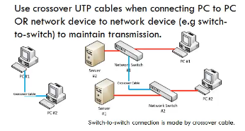
How to Connect Two Computers by Using Cross-Over Cable?

This section involves the connectivity of the computers through a cross over cable, without using the network devices like switch or hub. In this unit we are assuming that the user is having Windows operating system.


STEPS

  1. Switch ON the computers
  2. Connect both computers with a cross over cable(Cat 5/6) having RJ 45   connector crimped at its both ends.
  3. Go to control panel
  4. Click on network connections
  5. Right click on cable connections.
  6. Click properties
  7. Pick internet protocol (TCP/IP) & press properties.
  8. Click on choose following IP address IP address: 1 choose 192.168.1.1
  9. Network is 255.255.255.0
  10. Press ok and close  
  11. Now repeat the steps (1 to 10) on the other computer but choose different IP
  12. address say it is 192.168.1.2
  13. Now test the connection by using cmd command

      • Go to start
      • Click Run
      • Type cmd
      • Type ping IP address if you are on system with IP 192.168.1.1 (i.e. ping 192.168.1.2)
      • If it says time-out, that means that you don’t have a connection with other computer

Interconnectivity facilitates the data sharing among the computers. So, you are required to understand, “How to share the data among the computers, connected to each other in either mode i.e. wired or wireless ” Just follow the steps listed below and you will get the data shared among the computers, listed steps work for both wired and wireless connections

Friday 24 March 2023

Practical - 59 :- Create cabling in a lab with HUB/ Switch and lo Boxes and patch panel.


How to Connect Two Computers by Using Cross-Over Cable?

In This section involves the connectivity of the computers through a cross over cable, without using the network devices like switch or hub. However we will discuss the establishment of computer network by using the network devices in our subsequent section. In this Practical we are assuming that the user are having Windows operating system


STEPS

  1. Switch ON the computers
  2. Connect both computers with a cross over cable(Cat 5/6) having RJ 45
  3. connector crimped at its both ends.
  4. Go to control panel
  5. Click on network connections
  6. Right click on cable connections.
  7. Click properties
  8. Pick internet protocol (TCP/IP) & press properties.
  9. Click on choose following IP address IP address: 1 choose 192.168.1.1bNetwork is 255.255.255.0
  10. Press ok and close
  11. Now repeat the steps (1 to 10) on the other computer but choose different IP address say it is 192.168.1.2 
  12. Now test the connection by using cmd command

  • Go to start
  • Click Run
  • Type cmd
  • Type ping IP address if you are on system with IP 192.168.1.1 (i.e. ping
  • 192.168.1.2)
  • If it says time-out, that means that you don’t have a connection with other
  • computer

Inter connectivity facilitates the data sharing among the computers. So, you are required to understand, “How to share the data among the computers, connected to each other in either mode i.e. wired or wireless ” Just follow the steps listed below and you will get the data shared among the computers, listed steps work for both wired and wireless connections.


How to Connect Computers USING HUB / SWITCH 

In section 1.3.1 we discussed How to connect computers using cross over cable?  in this section we are extending the concept of the computers connectivity through network devices like hub/switches. The steps desired to be performed are given below:


  1. Connect the hub to the power source through its adapter and switch it ON
  2. Take Straight cables with RJ 45 connector connected to its both ends, use it to connect the Network Interface Card(NIC) of all computer system to the different ports of Hub/switch as shown in the figure below.

  3. Switch ON the computers
  4. Go to control panel
  5. Click on network connections
  6. Right click on cable connections.
  7. Click properties
  8. Pick internet protocol (TCP/IP) & press properties.
  9. Click on choose following IP address
  10. IP address: 1 choose 192.168.1.1 Network is 255.255.255.0
  11. Press ok and close
  12. Now repeat the steps (1 to 10) on the other computer but choose different IP address say 192.168.1.2 for second computer and so on.
  13. Now test the connection by using cmd command
    • Go to start
    • Click Run
    • Type cmd
    • Type ping IP address if you are on system with IP 192.168.1.1 (i.e. ping 192.168.1.2)
    • If it says time-out, that means that you don’t have a connection with other computer


Popular Posts