
I
Identifying Status of UPS from Front Panel Indicators
Key Technical Objectives
- Identify Utility Power (Line-On), Battery Mode, Bypass Mode, and Fault Statuses.
- Understand LED color codes (Green, Yellow/Amber, Red) and LCD status readings.
- Recognize audio alarm patterns corresponding to mains loss, overload, and low battery warnings.
- Perform basic diagnostic troubleshooting based on panel indications.
Tools, Equipment & Materials Required
| Item Description | Specification | Quantity |
|---|---|---|
| Online / Line-Interactive UPS | 600VA to 1KVA with LED/LCD Panel | 1 Unit |
| Digital Multimeter (DMM) | CAT-III 600V Rated | 1 Unit |
| Variable Test Load | Incandescent Lamp Bank / PC Monitor Load | 1 Set |
| Safety Gloves & Insulated Tools | Standard Electrical Grade | 1 Set |
Typical UPS Front Panel Layout Diagram
Figure 1.1: Standard UPS Control Panel with LED Indicators and LCD Display
Detailed Hardware Reference
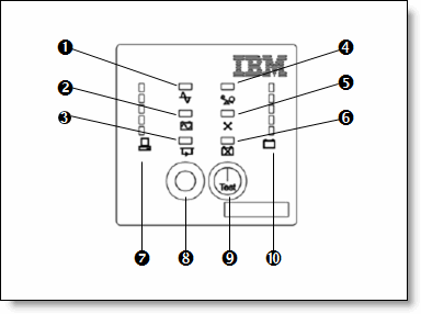
Figure 1.2: Industrial UPS Status Indicators and Load Level Bar Graph Layout
Practical Execution Procedure
Connect the UPS input cord to the main supply outlet. Ensure the battery breaker/switch is switched ON. Keep the load disconnected initially.
Switch ON the main supply power. Press the UPS Power button. Observe the steady Green LED indicator and record the LCD input voltage reading.
Turn OFF the AC main wall switch while keeping the UPS running. Observe the transition: Green LED turns off, Yellow/Amber LED illuminates, and an intermittent beep alarm sounds.
Connect additional test load exceeding rated capacity (or simulate overload mode). Observe the Red Fault LED illumination and continuous audio warning beep.
Trainee Observation Sheet
| Operating State | Green LED | Yellow LED | Red LED | Buzzer Sound | UPS Output Status |
|---|---|---|---|---|---|
| AC Line Normal | ON (Steady) | OFF | OFF | Silent | Normal 230V AC |
| Mains Power Failure | OFF | ON (Blinking) | OFF | Intermittent Beep | Inverter 230V AC |
| Low Battery State | OFF | ON (Fast Blink) | OFF | Rapid Beep | Output about to trip |
| Overload / Fault | OFF | OFF | ON (Steady) | Continuous Beep | Shut Down / Trip |
Safety Precautions & Troubleshooting Notes
- Never short-circuit the output terminals or battery leads of the UPS.
- Ensure load connected does not exceed the total VA rating of the UPS unit.
- If Fault LED (Red) lights up, disconnect the load immediately and check for short circuits or failed internal batteries.
Practical Conclusion
Result: Successfully identified and recorded various status indicators (Mains Normal, Battery Mode, Low Battery, and Fault Condition) on the UPS front panel. Verified output voltage parameters during each operational mode.





.jpg)


0 Comments
If you have any doubts, please let me know