Ideal Transformer
The ideal transformer has no losses.
There is no magnetic leakage flux, ohmic resistance in its windings and no iron loss in the core.
EMF Equation of Transformer

N1 – number of turns in primary.
N2 – number of turns in secondary.
Φm – maximum flux in weber (Wb).
T – time period. Time is taken for 1 cycle.
The flux formed is a sinusoidal wave. It rises to a maximum value Φm and decreases to negative maximum Φm. So, flux reaches a maximum in one-quarter of a cycle. The time taken is equal to T/4.
Average rate of change of flux = Φm/(T/4) = 4fΦm
Where f = frequency
T = 1/f
Induced emf per turn = rate of change of flux per turn
Form factor = rms value / average value
Rms value = 1.11 (4fΦm) = 4.44 fΦm [form factor of sine wave is 1.11]
RMS value of emf induced in winding = RMS value of emf per turn x no of turns
Primary Winding
Rms value of induced emf = E1 = 4.44 fΦm * N1
Secondary winding:
Rms value of induced emf = E2 = 4.44 fΦm * N2
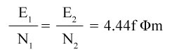
This is the emf equation of the transformer.
For an ideal transformer at no load condition,
E1 = supply voltage on the primary winding.
E2 = terminal voltage (theoretical or calculated) on the secondary winding.
Voltage Transformation Ratio

K is called the voltage transformation ratio, which is a constant.
Case1: if N2 > N1, K>1 it is called a step-up transformer.
Case 2: if N2< N1, K<1 it is called a step-down transformer.
Transformer Efficiency
Applications Of Transformer
- The transformer transmits electrical energy through wires over long distances.
- Transformers with multiple secondary’s are used in radio and TV receivers which require several different voltages.
- Transformers are used as voltage regulators.
Post a Comment
If you have any doubts, please let me know