Search This Blog

Wednesday, 27 December 2023

EXPERIMENT - 43 : - Explain the construction and working of MOSFET.

What is a MOSFET? 


Metal oxide semiconductor field effect transistors (MOSFETs) are electrical devices that switch or amplify voltages in circuits

  • It has an insulated gate that has the ability to change its conductivity with the applied voltage that is further used for amplifying or switching electrical signals. 
  • It's a voltage-controlled device. 
  • Traditionally, the structure of a metal oxide semiconductor (MOS) is obtained by growing a layer of silicon dioxide on top of a silicon substrate by thermal oxidation and depositing a layer of metal or polycrystalline silicon.
  • A metal-insulator-semiconductor field-effect transistor (MISFET) and insulated-gate field-effect transistor (IGFET) are termed almost synonymous with MOSFET.

Generally, MOSFET is a four-terminal device.  MOSFET terminals are labeled as follows:

  • Source
  • Gate
  • Drain
  • Body

Frequently the body is connected to the source terminal, reducing the terminals to three.


Construction of MOSFET


The typical MOSFET circuit diagram is as follows:

  • The MOSFET's base is made up of p-type semiconductors.
  • Both forms of the base are heavily doped with an n-type impurity, denoted by the symbol n+ in the diagram.
  • The terminal's source and drain come from the strongly doped portions of the base.
  • For insulation, a layer of silicon dioxide is applied to the substrate layer.
  • On top of the silicon dioxide, a thin insulated metallic plate works as a capacitor.
  • The thin metallic plate is removed, revealing the gate terminal.
  • A voltage source is then connected between these two n-type areas to construct a DC circuit.

Working Principle of MOSFET


The main working principle of a MOSFET device is to be able to control the current flow and voltage between the drain and source terminals. It works almost like a switch. A MOSFET's operation is dependent upon the MOS capacitor. The MOS capacitor is the heart of the MOSFET.
  • The semiconductor surface which is located between the source and drain terminal below the oxide layer can be inverted from n-type to p-type by the application of either negative or positive gate voltages respectively.
  • The holes present beneath the oxide layer are pushed downward with the substrate when a repulsive force is applied for the positive gate voltage.
  • The depletion region is populated by bound negative charges associated with the acceptor atoms.
  • A channel is developed when electrons are reached. Electrons are also attracted to the positive voltage from the n+ source and drained into the channel by that voltage.
  • As a result, if a voltage is applied between the drain and source, current flows freely between them, and the gate voltage controls electron flow.
  • If we apply a negative voltage, a hole channel will be formed under the oxide layer, instead of the positive voltage.

Types of MOSFET


The flowchart below shows how MOSFETs are classified based on their structure and materials.


  • There are two types of MOSFETs: Enhancement and Depletion
  • Each class is available in either n-channel or p-channel configurations, resulting in a total of four MOSFET categories.

Depletion Mode

The Depletion mode P-N channel has the highest conductivity when there is no voltage at the gate terminal. The channel conductivity diminishes when the voltage across the gate terminal is either positive or negative.

Enhancement Mode

The circuit does not work if there is no voltage across the gate terminal. When the maximum voltage is applied across the gate terminal, the device's conductivity improves. The abbreviation NMOS is used to refer to N-channel MOSFETs and the P-channel MOSFETs are abbreviated as PMOS, and the circuit looks as follows:


Thursday, 21 December 2023

PRACTICAL - 38 :- CMOS SETUP

AIM :- CMOS SET UP

PROCEDURE

THEORY

What is CMOS? 

Complementary metal-oxide semiconductor, or CMOS, typically refers to a battery-powered memory chip in your computer that stores startup information. Your computer's basic input/output system (BIOS) uses this information when starting your computer. CMOS-related error messages could be caused by a faulty or discharged battery. The battery can become discharged if your computer has been turned off for a very long time. To resolve CMOS-related errors, check the information that came with your computer or contact your computer manufacturer. Because your CMOS settings are specific to your computer's hardware, Microsoft can't provide specific instructions for changing them.

CMOS BIOS settings 

There are three company BIOS chips. They are Award, Phoenix and AMI. When you press Del or F2 or F10 key at system startup. These CMOS BIOS settings will be opened. Marked the keys and options. These are the keys to open BIOS settings at startup.                        


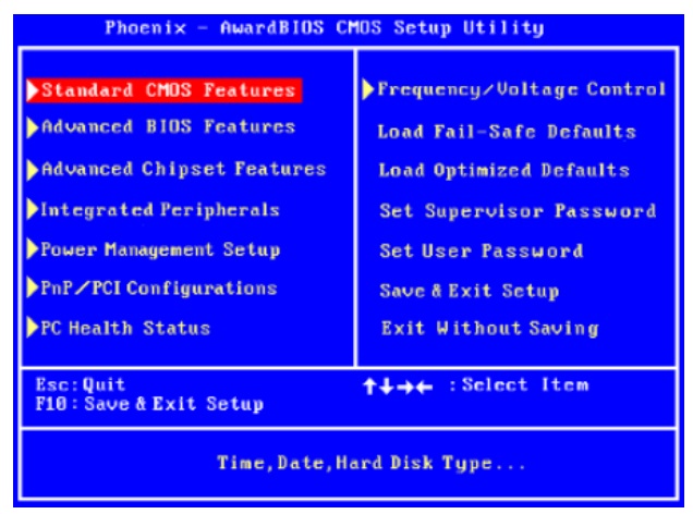
This is the Award BIOS options. they are Standard CMOS features, Advanced BIOS features, Advanced Chipset features, Integrated Peripherals, Power Management Setup, PnP/PCI configurations, PC Health Status, Frequency/Voltage Control, Load Fail-safe Defaults, Load Optimized Defaults, Set Supervisor Password, Set User Password, Save & Exit Setup and Exit Without Saving, and below the shortcut keys Esc to Quit, F10 to Save & Exit setup, Arrow keys to select Items.


This is the standard CMOS setting, in these settings, Date, Time settings, disk drive settings, how many drives have detected or not. in this motherboard, Hard drives connected to IDE channel 0 Master, that means Primary Master and DVD RW connected to IDE channel 4 Master. Floppy drive settings, if your system has floppy disk drives, you must enable Drive A, just like this. bottom of this window, there are some options to change settings.


These are the advanced settings. Hard disk boot priority settings for using more than one hard drive, select hard drive for boot. At the same CD-ROM boot priority. Important options are first boot and second boot devices. First boot always in Hard disk, but whenever you format your system, you must change first boot device as CD drive to boot from bootable CD.


These are the Advanced Chipset settings. These settings for Graphics purpose. Your system has Installed AGP cards, these settings are automatically enabled. But you have to select or change card memory here. 


These are the power management settings. These are all default settings. Don't change these settings.


PnP stands for Plug and Play. These are the Pnp/PCI configuration settings. These are also default settings. No need to change the settings. It will automatically take the settings, when you insert or install PCI cards.  


These are the PC health status settings. These are also default settings. No need to change the settings. 
These are Load fail safe defaults settings. Load fail safe default settings are used to restore the default settings of BIOS. 


Supervisor password is used to set password to all BIOS settings. To create password, just select the option and enter password and conformation. User password is used to login. This option is to view all BIOS settings. if you want to change option supervisor password is must. 


Last two options are used to save or not options. Save & exit option is saving your settings and without saving option is not saving option.

Step 1: Prepare Your PC

  1. Backup Important Data: Before making any changes in the BIOS/UEFI, ensure that you have backed up any important data, as incorrect settings can lead to system instability.
  2. Gather Information: Familiarize yourself with your motherboard's manual, as it often contains specific information about accessing and using the CMOS setup utility.

Step 2: Access the CMOS Setup Utility

  1. Restart Your Computer: If your PC is already on, restart it.
  2. Enter BIOS/UEFI: During the boot process, press the designated key to enter the BIOS/UEFI setup. Common keys include:
    • Delete (Del)
    • F2
    • F10
    • Esc
    • F12 (The specific key may vary based on the manufacturer; look for a prompt on the screen during startup.)

Step 3: Navigate the CMOS Setup Utility

  1. Use the Keyboard: Most BIOS/UEFI interfaces are navigated using the keyboard. Use the arrow keys to move through the menus, and the Enter key to select options.
  2. Explore Different Sections: Common sections you may find include:
    • Main: Basic system information (CPU, RAM, etc.)
    • Advanced: Advanced settings for hardware configuration.
    • Boot: Boot order and options.
    • Security: Password settings and security features.
    • Exit: Options to save changes or exit without saving.

Step 4: Modify Settings (If Necessary)

  1. Change Boot Order: If you want to boot from a USB drive or another device, navigate to the Boot section and adjust the boot priority.
  2. Enable/Disable Hardware Features: You can enable or disable features like virtualization, integrated peripherals, or power management settings.
  3. Set System Time and Date: Ensure the system clock is accurate by adjusting the date and time settings.

Step 5: Save and Exit

  1. Save Changes: If you made any changes, navigate to the Exit section and choose the option to save changes and exit (often labeled as "Save Changes and Exit" or similar).
  2. Reboot: Your computer will restart with the new settings applied.

Step 6: Study and Document

  1. Take Notes: Document any changes you made and their effects on system performance or behavior.
  2. Research Settings: If you encounter unfamiliar settings, research them online or refer to the motherboard manual for detailed explanations.

Step 7: Troubleshooting

  1. Reset to Default: If you encounter issues after making changes, you can return to the CMOS setup utility and load the default settings (often found in the Exit section).
  2. Clear CMOS: If necessary, you can clear the CMOS by using a jumper on the motherboard or removing the CMOS battery for a few minutes (refer to the motherboard manual for instructions).


Practical - 33:- Practice on Add on Cards, Cables & Connectors(identify I/O slot and connectors)

 AIM :-  Practice on Add on Cards, Cables & Connectors(identify I/O slot and connectors)

APPARATUS REQUIRED:

 Sl. no.     Name of Equipment 

1               Personal Computer

ROW MATERIAL REQUIRED :

Sl. no.     Name of Row Material     

1             AGP, PCI, SCSI, USB,NIC, FIREWIRE

PROCEDURE :-


now we learned about Add on Cards, Cable, and Connector ie. AGP, PCI , TV TUNER, SCSI, USB, NIC, fire wire, card reader.

The Accelerated Graphics Port (often shortened to AGP) is a high‐speed point‐to‐point channel for attaching a video card to a computer system, primarily to assist in the acceleration of 3D computer graphics. 

PCI Express (Peripheral Component Interconnect Express), officially abbreviated as PCIe, is a high‐speed serial computer expansion bus standard designed to replace the older PCI, PCI‐X, and AGP bus standards. 

A TV tuner card is a kind of television tuner that allows television signals to be received by a computer. Most TV tuners also function as video capture cards, allowing them to record television programs onto a hard disk much like the digital video recorder (DVR) does. 

A digital video recorder (DVR), sometimes referred to by the merchandising term personal video recorder (PVR), is a consumer electronics device or application software that records video in a digital format to a disk drive, USB flash drive, SD memory card, SSD or other local or networked mass storage device.

Video capture is the process of converting an analog video signal—such as that produced by a video camera or DVD player—to digital video. The resulting digital data are computer files referred to as a digital video stream, or more often, simply video stream.

The Small Computer System Interface (SCSI) is a set of parallel interface standards developed by the American National Standards Institute (ANSI) for attaching printers, disk drives, scanners and other peripherals to computers. 

USB (Universal Serial Bus) is the most popular connection used to connect a computer to devices such as digital cameras, printers, scanners, and external hard drives. USB is a cross‐platform technology that is supported by most of the major operating systems.


A network interface card (NIC) is a circuit board or card that is installed in a computer so that it can be connected to a network.

IEEE 1394 is an interface standard for a serial bus for high‐speed communications and isochronous real‐time data transfer. It was developed in the late 1980s and early 1990s by Apple, who called it FireWire.

A small USB plug‐and‐play device used to read, copy and backup data from portable flash memory cards such as an SD Card, MiniSD, MicroSD, SIM and others that are used in a wide variety of consumer electronics products.  One card reader may be used for a specific type of memory card, while others may be designed to read multiple types of memory cards.

Network‐attached storage (NAS) is a file‐level computer data storage server connected to a computer network providing data access to a heterogeneous group of clients. NAS not only operates as a file server, but is specialized for this task either by its hardware, software, or configuration of those elements.

Practical -32 :- Servicing of UPS by simulating more likely faults and systematic approach to identify and rectify them.

 AIM :- Servicing of UPS by simulating more likely faults and systematic approach to identify and rectify them.  

APPARATUS REQUIRED:

 Sl. no.     Name of Equipment 

1              UPS       

2               Trainee tool kit


Procedure :- 

Common Power Problems   Below are some common power problems and their general power protection solutions.  

Voltage Surges and Spikes

Surges: Sudden increases in electrical current through the line. Surges can be triggered by heavy equipment being turned off or by utility switching. Surges happen frequently but may not be noticed because they last such a short period of time. They can damage hardware and corrupt data. (Power protection solutions: UPS, surge suppressor or line conditioner) 

Spikes: Increase in voltage through the line for a very short period of time. The results can damage hardware and data. (Power protection solutions: UPS, surge suppressor or line conditioner)

Brownout or Voltage Sags A reduction in the incoming electrical current and the cause of most power problems. A computer has to work harder when it is not being supplied enough power creating more wear and shortening the life of critical components. (Power protection solutions: UPS or line conditioner)   

Blackouts or Power Failure Complete loss of power can cause the obvious problems of lost data and hardware damage. When power is restored one can also experience the power problems mentioned above: surges, spikes and voltage sags. (Power protection solutions: UPS)  

Frequency Variations Change in frequency stability. (Power protection solutions: UPS, surge suppressor or line conditioner).

Line Noise Signals that are embedded or overlaid onto incoming power. This usually doesn't damage hardware but can corrupt data. It is caused from the use of other electrical equipment or household appliances like microwaves, hairdryers or vacuum cleaners. (Power protection solutions: UPS, surge suppressor or line conditioner).  

To determine the requirements for a UPS generally involves a balance of cost vs. need. The components of a basic UPS system contain a battery charger/rectifier, batteries, and an inverter. The battery charger is a rectifier that converts AC power to DC in order to charge the batteries. The batteries store power that is supplied to the load when there is a loss or decrease of a certain tolerance of utility supply power. The inverter converts the DC power from the battery to AC power used to supply the load.


Servicing of UPS by simulating more likely faults and systematic approach to identify and rectify them.    


Practical -27 :- How To set up your sound card manually

 AIM :- How To Set Up Your Sound Card Manually

સાધનો - સાહિત્ય  :- PC with multimedia components


Procedure: now we learned about how to troubleshoot sound card.

1. Open your sound card's volume controls as follows: 

  1. On your computer's desktop, click Start.
  2. Point to Programs, point to Accessories, and then point to Entertainment. 
  3. Choose Volume Control.
2. On the Options menu, choose Properties.
3. Optional. If your computer has more than one sound card, in the Mixer device list, select the sound card that you want to use for recording. 
4. Select Playback, and then click OK. 
5. In the Volume Controls dialog box, ensure that the Microphone setting is either muted or not selected, depending on your sound card. 
6. On the Options menu, choose Properties again. 7. Select Recording, and then click OK.


1. In the Recording Control dialog box, ensure that the Microphone setting is either selected or not muted, depending on your sound card. Leave Recording Control dialog box open on your screen.

2. Start Windows Sound Recorder, as follows:
  1. On your computer's desktop, click Start. 
  2. Point to Programs, point to Accessories, and then point to Entertainment. 
  3. Choose Sound Recorder.
3. Use Sound Recorder to record your voice as you speak into the audio input device that you want to use when making the actual recording.    
4. While speaking, adjust the Microphone volume as necessary, using the Volume slider in the Recording Control dialog box. 
5. Play back yours's recording. 
6. If the audio is too low, increase the Microphone volume. If the audio is distorted, decrease the Microphone volume. 
7. If necessary, continue recording your voice and adjusting the Microphone volume. Use your sound card’s volume controls and Windows Sound Recorder to manually set up your sound card.