Translate

Search This Blog

Information Technology

ICTSM: The Unseen Force Behind Seamless Operations.

Industrial Visit

Beyond the Classroom, into the Industry. Connecting Theory to the Real World, Where Skills Get Real.

The Blueprint for Success is in Your Hands.

Hands-on Training for a Head-Start Career.

Technology Made Simple

The Expertise to Uncomplicate Your World.

Where Minds and Machines Connect.

Transforming Ideas into Digital Reality.

Thursday, 23 March 2023

Practical -61 :-Installing And Configure Peer-to-Peer Network with at least three hosts


Installing And Configure Peer-to-Peer Network with at least three hosts

  • Practical Significance

Identify and know the use of peer to peer network

Configure peer to peer network

  • Relevant Programs Outcomes (POs)

  1. Basic knowledge: Apply knowledge of basic mathematics, sciences and basic engineering to solve the broad-based Information Technology problems.
  2. Discipline knowledge: Apply Information Technology knowledge to solve Information Technology related problems.
  3. Experiments and practice: Plan to perform experiments and practices to use the results to solve broad-based Information Technology problems.
  4. Engineering tools: Apply relevant Information Technologies and tools with an Understanding of the limitations.
  5. Communication: Communicate effectively in oral and written form.

  • Competency and Practical skills

  1. Setup peer-to-peer Network

  • Relevant Course Outcomes

    1. Use Basic Concept of Networking for setting of Computer Network
    2. Setup up computer Network for Specific Requirement

  • Practical Outcomes (POs)

              Connect computers in Peer-to-Peer Network

  • Relevant Affective Domain Related Outcomes

  1. Follow safety practices
  2. Demonstrate working as a leader/team member
  3. Follow ethical practices

  • Minimum Theoretical Background

In Peer to Peer architecture every node is connected to other node directly for exchanging information instead of connected to central server                                          

Every computer node is referred as peer and they do the job of client as well as server both.                                                                                                                            

Every peer provides services to other peers as well as uses services provided by other peers.


Configuring peer to peer network

“Crossover cable is used”

One end is used for transmitting and other end for receiving data. Peer-to-Peer networking is when all computers are on the same network. They are considered as peers and will have to be connected to a hub, switch or a router. There is no server, controller or one in charge. Computers in a workgroup shares resources such as the printer and files. Workgroup is automatically set up when you set up a network and they all share the same subnet. A work group is not protected by a password, no security is provided

  • Diagrams / Experimental set-up /Work Situation


1. Click Start Menu > Control Panel > Network and Sharing Center. Click Change adapter settings.

2. Right-click on Local Area Connection and click on Properties.


3. Select Internet Protocol Version 4 (TCP/IPv4) and click on Properties.

Select "Use the following IP address" and enter the IP address, Subnet Mask and DNS server.

Click OK and close the Local Area Connection properties window.

 How Workgroup works

A computer joining a workgroup is assigned to the same workgroup name this process makes Accessing the computers easier.

 How to create a workgroup


Click on Start button Right-click on Computer and then click Properties 2 Under Computer name, domain, and workgroup settings, click Change settings.


Peer-to-peer applications.


  • Skype, an Internet telephony network, uses P2P technology.
  • Instant messaging systems and online chat networks.
  • Bitcoin and PPCoin are peer-to-peer-based digital currencies.
  • Dalesa a peer-to-peer web cache for LANs (based on IP multicasting).
  • Open Garden, connection sharing application that shares Internet access with other
  • devices using Wi-Fi or Bluetooth.
  • Streaming media. P2PTV and PDT

Precaution

  • Handle Computer System and peripherals with care
  • Follow Safety Practices


Practical - 68 :- Install TCP/IP protocol and configure Advanced features of TCP/IP Protocols like IP address,Subnet mask,gateway, primary and secondary DNS


AIM: Install TCP/IP protocol and configure Advanced features of     

         TCP/IP Protocols like IP address,Subnet mask,gateway,       

         primary and secondary DNS


I. Practical Significance

    Install TCP/IP protocol with advanced features

II. Relevant Programs Outcomes (POs)

  1. Basic knowledge: Apply knowledge of basic mathematics, sciences and basic engineering to solve the broad-based Information Technology problems.
  2. Discipline knowledge: Apply Information Technology knowledge to solve Information Technology related problems.
  3. Experiments and practice: Plan to perform experiments and practices to use the results to solve broad-based Information Technology problems.
  4. Engineering tools: Apply relevant Information Technologies and tools with an understanding of the limitations.
  5. Communication:Communicate effectively in oral and written form.

III. Competency and Practical skills

  1. Setup Network with TCP/IP protocol

IV. Relevant Course Outcomes

  • Use Basic Concept of Networking for setting of Computer Network
  • Configure TCP/IP services
  • Implement Sub netting for improved Network address Management

V. Practical Outcomes (POs)

    Install TCP/IPProtocol

VI. Relevant Affective domain related Outcomes

    1. Demonstrate working as a leader/team member

    2. Follow ethical practices

VII. Minimum Theoretical Background

Protocol:

It is a set of rules and conventions used for communication between network devices.

Protocols include mechanisms for devices to identify and make connections with each other, as well as formatting rules that specify how data is packaged into messages sent and received.

Some protocols also support message acknowledgement and data compression designed for reliable and/or high-performance network communication.

It determines the type of error checking to be used. Transmission control protocol (TCP), Internet protocol (IP), Hyper Text Transfer Protocol (HTTP), File transfer protocol (FTP) etc.

TCP/IP:

  • Transmission Control protocol/internet Protocol, used to connect computers on the Internet or network.
  • TCP/IP is built into the UNIX Operating system and is used by the Internet, making it the de facto standard for transmitting data over networks.
  • Transmission Control Protocol, manages the assembling of a message or file into smaller packets that are transmitted over the Internet and received by a TCP layer that reassembles the packets into the original message.
  • Internet Protocol, handles the address part of each packet so that it gets to the right destination.
  • TCP/IP protocols map to a four-layer conceptual model known as the DARPA model, named after the US Government agency that initially developed TCP/IP. The four layers of the DARPA model are: Application, Transport, Internet, and Network Interface.

IP address:

  • An Internet Protocol address (IP address) is a numerical label assigned to each device (e.g., computer, printer) participating in a computer network that uses the Internet Protocol for communication.
  • An IP address is an identifier for a computer or device on a TCP/IP network. Two versions of the Internet Protocol (IP) are in use: IP Version4 (IPv4) and IP Version6 (IPv6).
  • IPv4 addresses are of 32 bits that are canonically represented in dot-decimal notation, which consists of four decimal numbers, each ranging from 0 to 255, separated by dots, e.g.,172.16.254.1
  • IPv6 addresses are of 128 bits that are represented as eight groups of four hexadecimal digits separated by colons. e.g. 2001:0db8:85 a3:0042:1000 :8a2e: 0370:7334
  • The IPv4 address space can be subdivided into 5 classes Class A, B, C, D and E. Each class consists of a contiguous subset of the overall IPv4 address range.


VIII. Diagrams / Experimental set-up /Work Situation


X. Procedure 

  1. Complete the following steps to install and configure the TCP/IP protocol.
  2. Start->Control Panel->Network and Internet->Network Sharing center, Change adapter setting
  3. Right-click the connection to which you want to add a network component, and then click Properties.
  4. If Internet Protocol (TCP/IP) is listed, skip to Step 6. If Internet Protocol (TCP/IP) is not listed, click Install.
  5. In the Select Network Component Type dialog box, click Protocol, and then click Add.
  6. From the Network Protocol list, select TCP/IP Protocol and click OK.
  7. From the General tab (for local area connections) or the Networking tab (for all other connections), select Internet Protocol (TCP/IP), and then click Properties.
  8. Configure TCP/IP either automatically or manually.

Automatically – You can automatically configure TCP/IP services if you have a DHCP server on your network. This automatic process ensures easy and accurate installation of TCP/IP because your local computer is configured with the correct IP address, subnet mask, and default gateway.

To configure automatically, select Obtain an IP address automatically, and then click OK.

Manually – You must configure TCP/IP manually if you do not have a DHCP server on your network, or if you are configuring a Windows server to be a DHCP server. In this case, you must manually enter valid addressing information after the TCP/IP protocol software is installed on your computer. To avoid duplicate addresses, be sure to use the values for IP addresses and subnet masks that are supplied by your network administrator.

To configure manually, select Use the following IP address, specify the necessary parameters, and then click OK.

XI. Precaution

1. Handle Computer System and peripherals with care

2. Follow Safety Practices


Tuesday, 21 March 2023

Practical -60 :- Rack Mounting the Switch


Bracket holes are horizontally equidistant, allowing bracket placements where the flange is not flush with either panel (Figure 3-2 on page 8). This placement supports a center-rack mount. After completing the instructions for your rack type.


Rack Mounting the Switch


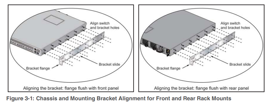
Two-Post Rack Mount To mount the switch onto a two-post rack, assemble the mounting brackets to the chassis, then attach the brackets to the rack posts. The accessory kit includes the following two-post mounting parts:

• 2 mounting brackets

• 12 M4x5 flat head Phillips screws

Refer to Figure 3-1 on page 7 and Figure 3-2 for a description of the mounting brackets. The switch supports any mounting position into a two-post rack that meets the following conditions:


• The bracket flanges do not extend beyond the switch chassis.

• Three sets of screws attach each mounting bracket to the chassis..

Figure 3-3 displays proper bracket mount configuration examples. Figure 3-4 displays improper bracket mount configuration examples.


Attaching Mounting Brackets to the Chassis

To attach mounting brackets to the switch chassis, perform this procedure:

Step 1 Align the mounting brackets with the chassis to obtain the desired mounting position.

Step 2 Attach the brackets with six M4x5 flat head Phillips screws per bracket, using a #1 Phillips screwdriver.

Space the screws evenly, separating them with the widest possible distance. Figure 3-5 displays screw placement for the front and center mount positions.


Inserting the Switch into the Rack

Step 1 Lift the chassis into the rack. Position the flanges against the rack posts.

Figure 3-6 displays the front-mount switch installation.


Step 2 Select mounting screws that fit your equipment rack.

Step 3 Attach the bracket flanges to the rack posts. After completing the two-post rack mount, proceed to : Cabling the Switch.


Four-Post Rack Mount

The switch is mounted onto a four-post rack by assembling two rails onto the rear posts, sliding the

switch onto the rails, then securing the switch to the front post.

The installation kit provides the following four-post mounting parts:

• 2 mounting brackets

• 2 rails

• 12 M4x5 flat head Phillips screws

Refer to Figure 3-1 on page 7 and Figure 3-2 on page 8 for a description of the mounting brackets.

The switch supports any mounting position where at least three sets of screws attach each mounting

bracket to the switch chassis.

Figure 3-7 displays proper bracket mount configuration examples. Figure 3-8 displays an improperbracket mount configuration example.


Attaching Mounting Brackets to the Chassis

To attach mounting brackets to the switch chassis, perform this procedure:

Step 1 Align the mounting brackets with the chassis to obtain the desired mounting position.

Step 2 Attach the brackets with six M4x5 flat head Phillips screws per bracket, using a #1 Phillips screwdriver.

Space the screws evenly, separating them with the widest possible distance. Figure 3-9 on  displays screw placement for the front mount and center mount positions.


Assembling the Rails onto the Equipment Rack The rails attach to the rear rack posts to support the switch. Before attaching the rails to the rack posts, verify that, when the switch is mounted, the distance between the bracket flanges and rail flanges does not exceed 30 inches, as shown in Figure 3-10.


To attach the rails to the rear rack post, perform this procedure:


Step 1 Select mounting screws that fit your equipment rack. Each rail requires two screws.

Step 2 Attach the rails to the rear rack posts, as shown in Figure 3-11


Attaching the Switch to the Rack


Step 1 Lift the switch into the rack and insert the mounting brackets onto the rails (Figure 3-12)


Step 2 Slide the switch on the rails, toward the rear posts, until the mounting bracket flanges are positioned on the rail posts.

Step 3 Select mounting screws that fit the equipment rack. Each chassis side requires two screws.

Step 4 Verify the distance between the mounting bracket flanges and rail flanges does not exceed 30 inches (Figure 3-10).

Step 5 Attach the bracket flanges to the rack posts (Figure 3-13).


Practical -57 :- Punching Practice IN IO Box and Patch Panel


Punching Down a Jack

Strip back the cable jacket. 

You should leave about 2.5 inches (6 cm) at the end of the cable. Insert the cable into the cable stripping tool or modular crimping tool and spin it around a few times. You should see that the jacket is cut. Remove the jacket.

 \


  • Stripping back the cable will help you remove the jacket to expose enough of the cable so you can separate it.

Expose the wires. You should have a few inches of exposed cable once you remove the cable jacket. Gently pull away the wire pairs from the center of the cable so they fan out. Separate the wire pairs by twisting in a counterclockwise motion. 

  • Try to straighten the ends as much as you can since this can make them easier to terminate.


Place the cable wires in the jack. Take the protective cover off the top of the jack and set the cable into the block of the jack. Insert each wire (conductor) into its own separate slot, making sure that the wire matches the A or B configuration. The conductor wires should be extending out of the jack.

  • Consider whether or not you want to use the T568A or T568B wiring scheme. The T568B is becoming more popular since it can be used with older color codes as well as newer codes.


Terminate the conductor wires. 

Take your punch down tool and press it down on the conductor wires to cut them. The angled (cut) part of the blade should come into contact with the shoulder (the long sturdy side of the jack). This will also make sure the wires that are cut are flush with the jack.

  • Be sure to punch straight down and not at an angle. This will prevent the jack from bending.
  • You should hear a loud click when you punch down. This just means that you've terminated the wire correctly.


 Inspect the wires.

Once you've finished terminating the wires, look at each wire to make sure there is no overhang out the side of the jack. You should also make sure that the edge of the cable jacket is near the base of the jack and the wires you just terminated. The wires should be securely in place.

If you notice wires sticking out the side, take a wire cutter and carefully trim the wire so that it's flush with the jack.

Place a dust cap on the jack.

Snap the dust caps in place so that the wires are protected. This will keep the connection secure and can prevent strain on the wires. You can easily remove the dust cap if you need to make changes to wiring later. Simply pop off the dust cap using a flat-head screwdriver inserted into the indentation on the side

  • If you can't set the dust caps back on the jack, your wires may not be seated correctly. Check the wires again to make sure they are secure and trimmed.


Choosing a Punch Down Tool


Find a basic hand-powered punch down tool. If you'll only occasionally be terminating wires, you can find a simple punch down tool that relies on pressure to trigger a cutting mechanism.

  • These are usually the least expensive and you can purchase replacement blades if they become dull.
  • 110, 66, and krone are the main different types of punch down tools. The 66 punch down tool is mainly used to terminate wires for Cat3, while the 110 punch down tool is used for terminating blocks for Ethernet cables. The krone punch down tool is great for installing and terminating Cat3, Cat5, Cat6.


Consider buying a battery-powered punch down tool. 


If you'll be terminating lots of wires or need to do it quickly, you may want to use a battery-powered punch down tool. These usually come with lithium batteries that don't require much charging.

  • You can choose the voltage for your punch down tool as well as whether or not you'd like to buy replacement blades. You may want to buy the extra blades if you'll be terminating a lot of wires.


Get a multi-wire punch down tool.
 You might find that you're still terminating so many wires that a standard punch down tool can't keep up with the work. Multi-wire punch tools work by terminating several pairs of twisted wires so you can terminate more wire more quickly.

  • Multi-wire punch down tools are also more efficient than standard punch down tools. They can also decrease hand fatigue which is more common in standard punch tools.