ICTSM: The Unseen Force Behind Seamless Operations.
.jpeg)
Beyond the Classroom, into the Industry. Connecting Theory to the Real World, Where Skills Get Real.

Hands-on Training for a Head-Start Career.

The Expertise to Uncomplicate Your World.

Transforming Ideas into Digital Reality.

A Voltage Dependent Resistor (VDR), also known as a Varistor, is a variable resistor whose resistance changes in relation to the applied voltage.
Under normal operating voltages, a VDR exhibits very high resistance and allows only a small leakage current to pass.
When the applied voltage exceeds the clamping voltage (threshold), the VDR's resistance drops dramatically.
This creates a low-resistance path, causing a large avalanche current to flow through the varistor, thereby diverting the surge away from the protected circuit components.
The relationship between current and voltage in a VDR is non-linear and similar to that of a diode.
Below the clamping voltage, the current is very small (standby/leakage current).
Above the clamping voltage, the current increases sharply and non-linearly with a small change in voltage.
Metal Oxide Varistor (MOV): This is the most common type.
Silicon Carbide Varistors: Made from sintered silicon carbide, these are suited for high-power and high-voltage applications. Their main drawback is a high standby current, which leads to significant power dissipation.
Clamping Voltage: The voltage at which the varistor begins to conduct significantly.
Maximum Rated AC/DC Voltage: The maximum continuous voltage the VDR can handle without damage.
Maximum Pulse Energy: The maximum energy (in joules) the VDR can absorb from a single surge.
Peak Current: The maximum surge current the VDR can withstand.
Standby Current: The small leakage current that flows through the VDR under normal operating voltage.
Degradation: Repeated exposure to voltage surges can lower the clamping voltage of a varistor over time.
Safety: This degradation can eventually lead to a short circuit, creating a fire hazard.
Use a varistor with a sufficiently high clamping voltage for the application.
Connect a thermal fuse in series with the VDR.

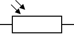
LDRs are made from high-resistance semiconductor materials (e.g., Cadmium Sulfide).
In the dark, the material has very few free charge carriers, resulting in extremely high resistance (up to 1 MΩ).
When light (photons) strikes the semiconductor, its energy excites bound electrons, allowing them to jump into the conduction band and become free charge carriers.
This increase in free carriers dramatically lowers the material's resistance (down to a few hundred ohms in bright light).
Intrinsic Photoresistors: Made from pure, un-doped semiconductors like Silicon or Germanium. They generally have lower sensitivity.
Extrinsic Photoresistors: Constructed from semiconductors doped with impurities. Doping enhances the photoconductive effect, resulting in higher sensitivity to light.
Sensitivity: Refers to how the LDR's resistance changes relative to light intensity. This relationship is non-linear. The sensitivity can also be affected by temperature, so the Maximum Power Dissipation is an important parameter.
Dark Resistance: The resistance in complete darkness.
Typical Resistance: Resistance at a specified light level.
Wavelength Dependence: LDRs exhibit varying sensitivity to different wavelengths (colors) of light, described by a spectral response curve. Most are designed to be sensitive to the visible light spectrum.
Peak Wavelength: The wavelength at which the LDR is most sensitive.
Latency (Response Time): The change in resistance is not instantaneous.
Rise Time: It can take up to a second for the resistance to rise to its maximum value when light is removed (dark situation).
Fall Time: The resistance drops much faster, typically around 10 ms, upon illumination.
Due to their high latency and susceptibility to thermal effects, LDRs are not ideal for applications requiring high precision or speed.
Photodiodes and phototransistors are active components with true PN junctions. They offer much sharper sensitivity and significantly lower latency (faster response times).
LDRs remain useful in simple, non-critical circuits where the goal is only to detect a general light vs. dark state. A unique application is in audio compressors, where their slow latency is beneficial for smoothing audio signals.
A thermistor (a portmanteau of "thermal resistor") is a type of resistor whose resistance is intentionally designed to vary significantly and predictably with temperature. This property makes them ideal for use as temperature sensors and in circuits that need to react to temperature change.
Thermistors are broadly classified into two main types based on their response to temperature:

NTC (Negative Temperature Coefficient)
PTC (Positive Temperature Coefficient)
An NTC thermistor exhibits a decrease in electrical resistance as its temperature increases. This relationship is inverse and highly non-linear.
At low temperatures: The thermistor has high resistance.
At high temperatures: The thermistor has low resistance.
NTC thermistors are typically made from a sintered mixture of semiconductor materials, such as metallic oxides of manganese (Mn), nickel (Ni), cobalt (Co), copper (Cu), and iron (Fe).
In these semiconductor materials, the charge carriers (electrons and holes) are responsible for conducting electricity. At low temperatures, most charge carriers are bound within the atomic structure, resulting in fewer free carriers and thus high resistance. As the temperature rises, thermal energy excites the electrons, causing them to break free from their valence bands and become available for conduction. This increase in the number of free charge carriers leads to a significant drop in resistance.

The relationship between resistance (R) and temperature (T) for an NTC thermistor is exponential.
A common and useful approximation for this curve is the Beta () Parameter Equation:
Where:
R(T) is the resistance at the temperature T (in Kelvin, K).
R_0 is the nominal resistance at a reference temperature T_0 (e.g., 10textkOmega at $25^\\circ\\text{C}$ or 298.15textK).
T_0 is the reference temperature in Kelvin (K).
beta (Beta) is the material constant (in Kelvin, K), typically ranging from 3000 K to 5000 K. It defines the "steepness" of the resistance curve.
For higher accuracy, the Steinhart-Hart Equation is used:
Where A, B, and C are coefficients derived from experimental measurements.
The standard symbol for a thermistor indicates its temperature dependency with a -T°.
The high sensitivity of NTC thermistors makes them ideal for:
Precise Temperature Sensing: Used in digital thermometers, thermostats (in air conditioners, refrigerators), and medical equipment.
Inrush Current Limiting: When a circuit is first turned on, the NTC is cold (high resistance), which limits the initial surge of current. As it warms up from the current flow, its resistance drops to a very low level, allowing normal circuit operation with minimal power loss.
Temperature Compensation: Used to counteract the effect of temperature on other electronic components in a circuit.
A PTC thermistor exhibits an increase in electrical resistance as its temperature increases. This effect is typically non-linear and can be extremely dramatic in "switching" type PTCs.
At low temperatures: The thermistor has low resistance.
At high temperatures: The thermistor has high resistance.
There are two main types of PTC thermistors:
Silistors: Made from doped polycrystalline silicon. They show a relatively gradual, linear increase in resistance with temperature. They are less common than the switching type.
Switching Type (Polymer PTC): These are more common and are composite materials made from a polymer matrix loaded with conductive particles (e.g., carbon black).
Normal Operation (Low Temp): The polymer is in a crystalline state. The carbon particles are packed closely together, forming numerous conductive paths. The overall resistance is very low (e.g., $\< 1 \\Omega$).
Tripping (High Temp): When the temperature rises to a specific point, called the Curie Temperature (), the polymer matrix undergoes a phase transition and expands rapidly. This expansion separates the conductive carbon particles, breaking the conductive paths. As a result, the resistance increases abruptly by several orders of magnitude (e.g., to 10textkOmega), effectively becoming an open circuit.
The resistance-temperature curve for a switching PTC is highly non-linear. It is characterized by a very sharp increase in resistance around its specified Curie Temperature (T_C).
The symbol is similar to the NTC but with a +T° to indicate a positive coefficient.
The unique switching characteristic of PTCs makes them suitable for:
Overcurrent Protection (Resettable Fuses): This is their primary application. A PTC is placed in series with the load. During normal operation, its resistance is negligible. If an overcurrent fault occurs, the PTC heats up rapidly due to I2R heating. When it reaches its T_C, its resistance skyrockets, limiting the current to a safe, low level. When the fault is cleared and the device cools down, the PTC returns to its low-resistance state, "resetting" the circuit.
Self-Regulating Heaters: A PTC can act as its own thermostat. As it heats up, its resistance increases, which in turn reduces the current flowing through it and limits its own power dissipation (). It will stabilize at a specific temperature.
Time Delay Circuits: The time it takes for a PTC to heat up and "trip" can be used to create simple time delays, for example, in the degaussing coil of older CRT monitors.
| Feature | NTC Thermistor | PTC Thermistor |
| Full Name | Negative Temperature Coefficient | Positive Temperature Coefficient |
| Core Behavior | Resistance decreases as temperature increases. | Resistance increases as temperature increases. |
| Material | Semiconductor (Metal Oxides) | Doped Polysilicon or Polymer Composite (Carbon in Polymer) |
| R vs. T Curve | Exponential decay (smooth, continuous) | Sharp, sudden increase at a specific point (the Curie Temperature) |
| Key Parameter | Beta (beta) value | Curie Temperature (T_C) |
| Primary Use | Temperature Sensing, Inrush Current Limiting | Overcurrent Protection (Resettable Fuse), Self-Regulating Heaters |
Advantages:
High Sensitivity: A small change in temperature results in a large change in resistance, making them very sensitive.
Low Cost: They are generally inexpensive to manufacture.
Fast Response Time: Due to their small size, they can react quickly to temperature changes.
Small Size: Can be integrated into compact electronic assemblies.
Disadvantages:
Non-Linearity: Their resistance-temperature relationship is not linear, often requiring complex calculations or lookup tables for precise measurements.
Limited Temperature Range: They typically operate within a narrower temperature range (e.g., -50°C to 200°C) compared to other sensors like thermocouples.
Self-Heating: The current flowing through the thermistor to measure its resistance will dissipate power (), causing it to heat up. This self-heating can introduce errors in the temperature reading if not properly accounted for.
Fragility: Ceramic-based thermistors can be more fragile than metal-based sensors like RTDs or thermocouples.