
Voltage Dependent Resistor (VDR)
1. Definition and Basic Function

A Voltage Dependent Resistor (VDR), also known as a Varistor, is a variable resistor whose resistance changes in relation to the applied voltage.
2. Working Principle
Under normal operating voltages, a VDR exhibits very high resistance and allows only a small leakage current to pass.
When the applied voltage exceeds the clamping voltage (threshold), the VDR's resistance drops dramatically.
This creates a low-resistance path, causing a large avalanche current to flow through the varistor, thereby diverting the surge away from the protected circuit components.
3. Voltage-Current (V-I) Characteristics
The relationship between current and voltage in a VDR is non-linear and similar to that of a diode.
Below the clamping voltage, the current is very small (standby/leakage current).
Above the clamping voltage, the current increases sharply and non-linearly with a small change in voltage.
4. Types of VDR
Metal Oxide Varistor (MOV): This is the most common type.
It consists of a sintered matrix of zinc oxide (ZnO) grains, which collectively act like a network of series and parallel connected semiconductor junctions. Silicon Carbide Varistors: Made from sintered silicon carbide, these are suited for high-power and high-voltage applications. Their main drawback is a high standby current, which leads to significant power dissipation.
5. Key Performance Indicators
Clamping Voltage: The voltage at which the varistor begins to conduct significantly.
Maximum Rated AC/DC Voltage: The maximum continuous voltage the VDR can handle without damage.
Maximum Pulse Energy: The maximum energy (in joules) the VDR can absorb from a single surge.
Peak Current: The maximum surge current the VDR can withstand.
Standby Current: The small leakage current that flows through the VDR under normal operating voltage.
6. Important Application Considerations
Degradation: Repeated exposure to voltage surges can lower the clamping voltage of a varistor over time.
Safety: This degradation can eventually lead to a short circuit, creating a fire hazard.
To mitigate this risk, it is crucial to: Use a varistor with a sufficiently high clamping voltage for the application.
Connect a thermal fuse in series with the VDR.
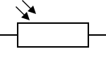
Light Dependent Resistor (LDR)
1. Definition and Basic Function

A Light Dependent Resistor (LDR), also called a Photoresistor, is a resistor whose resistance varies with the intensity of incident light.
2. Working Principle (Photoconductivity)
LDRs are made from high-resistance semiconductor materials (e.g., Cadmium Sulfide).
In the dark, the material has very few free charge carriers, resulting in extremely high resistance (up to 1 MΩ).
When light (photons) strikes the semiconductor, its energy excites bound electrons, allowing them to jump into the conduction band and become free charge carriers.
This increase in free carriers dramatically lowers the material's resistance (down to a few hundred ohms in bright light).
3. Types of LDR
Intrinsic Photoresistors: Made from pure, un-doped semiconductors like Silicon or Germanium. They generally have lower sensitivity.
Extrinsic Photoresistors: Constructed from semiconductors doped with impurities. Doping enhances the photoconductive effect, resulting in higher sensitivity to light.
4. Key Performance Indicators
Sensitivity: Refers to how the LDR's resistance changes relative to light intensity. This relationship is non-linear. The sensitivity can also be affected by temperature, so the Maximum Power Dissipation is an important parameter.
Dark Resistance: The resistance in complete darkness.
Typical Resistance: Resistance at a specified light level.
Wavelength Dependence: LDRs exhibit varying sensitivity to different wavelengths (colors) of light, described by a spectral response curve. Most are designed to be sensitive to the visible light spectrum.
Peak Wavelength: The wavelength at which the LDR is most sensitive.
Latency (Response Time): The change in resistance is not instantaneous.
Rise Time: It can take up to a second for the resistance to rise to its maximum value when light is removed (dark situation).
Fall Time: The resistance drops much faster, typically around 10 ms, upon illumination.
5. LDR vs. Photodiodes and Phototransistors
Due to their high latency and susceptibility to thermal effects, LDRs are not ideal for applications requiring high precision or speed.
Photodiodes and phototransistors are active components with true PN junctions. They offer much sharper sensitivity and significantly lower latency (faster response times).
LDRs remain useful in simple, non-critical circuits where the goal is only to detect a general light vs. dark state. A unique application is in audio compressors, where their slow latency is beneficial for smoothing audio signals.


0 Comments
If you have any doubts, please let me know