Meaning and Application of resonance. Series and parallel resonance circuits.
The specialty of this LC network is its property, known as resonance. Whenever an inductor and a capacitor are connected in parallel as shown in Fig 1 or in series as shown in Fig 2, the circuits exhibit a special phenomenon known as resonance. Resonance, in simple terms, means, the ability to select a particular frequency from the fed signal consisting of signals of different frequencies (wide band of frequencies)
Impedance of series resonance circuit
A simple series LC circuit shown in Fig 3a. In this series LC circuit
- Resistance R is the total resistance of the series circuit (interna1 resistance) in ohms,
- XL is the inductive reactance in ohms, and
- Xc is the total capacitive reactance in ohms.
All though the unit of measure of reactance and resistance Is the same(ohms) the impedance, Z of the circuit is not given by the simple addition of R, XL and Xc. This is because, XL is +90° out of phase with R and Xc is ‐900 out of phase. with R. Hence the impedance Z of the circuit is the phasor addition of the resistive and reactive components as shown by dotted lines in Therefore, Impedance Z of the circuit is given by,
Note that the applied voltage is not equal to the sum of voltage drops across reactive component X and resistive component. This is again because the voltage drops are not in phase. But the phasor sums of VR, and VX, will be equal to the applied voltage as given below,
In this condition, the impedance Z of the circuit will not only be purely resistive but also minimum. Since the reactance of Land Care frequency dependent, at some particular frequency say f,, the inductive reactance X, becomes equal to the capacitive reactance XC. In such a case, since the impedance of the circuit will be purely resistive and minimum, current through the circuit will be maximum and will be equal to the applied voltage divided by the resistance R.
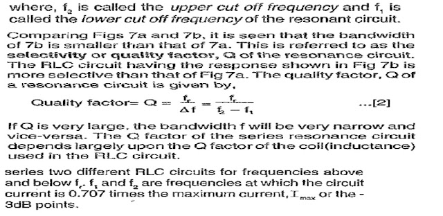
Selectivity or Q factor of a series RLC circuit Indicates that series RLC circuits select a band of frequencies around the resonant frequency, f,. This band (f1 to f2 is called the band width f of the series RLC, circuit.
Application of series resonance circuits A series resonance circuit can be used in any application where it is required to select a desired frequency.
Used in wave trap circuits A wave trap is a resonant LC circuit tuned to the frequency to be rejected.
Used for rejecting unwanted frequencies.
PARALLEL RESONANCE
The circuit at Fig 1, having an inductor and a capacitor connected in parallel is called parallel LC circuit or parallel.
resonance circuit. The resistor R, shown in dotted lines indicate the internal dc resistance of the coil L. The value of R will be so small compared to the inductive reactance, that it can be neglected From Fig it can be seen that the voltage across Land C is same and is equal to the input voltage Vs.
Zero current in the circuit means that the impedance of the parallel LC is infinite. This condition at which, for a particular frequency, f,, the value of X, = X,, the parallel LC circuit is said to be in parallel resonance.
Zero current in the circuit means that the impedance of the parallel LC is infinite. This condition at which, for a particular frequency, f,, the value of XL = XC the parallel LC circuit is said to be in parallel resonance Summarizing, for a parallel resonant circuit, at resonance
In a parallel resonance circuit, with a pure L (no resistance) and a pure C(loss‐less), at resonance the impedance will be infinite. In practical circuits, however small, the inductor will have some resistance. Because of this, at resonance, the phasor sum of the branch currents will not be zero but will have a small value I. This small current I will be in phase with the applied voltage and the impedance of the circuit will be very high although not infinite.
Summarizing, the three main characteristics of parallel resonance circuit at resonance are, ‐ phase difference between the circuit current and the applied voltage is zero ‐ maximum impedance ‐ Minimum line current. The variation of impedance of a parallel resonance circuit with frequency is shown in Fig 2.
Bandwidth of parallel resonant circuits The bandwidth of a parallel resonant circuit Is also defined by the two points on either side of the resonant frequency at which the value of impedance Zp drops to 0.707 or of its maximum value at resonance as shown the bandwidth of the parallel resonance
The selectivity or Q‐factor for a parallel resonance circuit is generally defined as the ratio of the circulating branch currents to the supply current and is given as:
Application of parallel resonant circuits
Parallel resonance circuits or circuits. Tank circuits are used as collector load in class‐C amplifiers instead of a resistor load
- blocking of freq, filtering
- selecting of freq for stability
- tank Ckt presents a high impedance to narrow range of frequency.


Post a Comment
If you have any doubts, please let me know