A universal gate, such as a NOR gate and NAND gate, can perform any Boolean function independently. This means these gates can form any logical Boolean expression on their own, simplifying circuit design.
In practice, this is advantageous since NOR and NAND gates are economical and easier to fabricate than other logic gates. So much so that an AND gate is typically implemented as a NAND gate followed by an inverter (not the other way around)! Similarly, an OR gate is typically realised as a NOR gate followed by an inverter.
ther logical gates – such as AND gates, NOT gates and OR gates – do not have this property of universality. Note that combined these three logic gates can implement all of the possible Boolean switching functions, but not individually. Hence unlike the NOR and NAND logic gates, they are not classified as universal gates.
If you which to play around with these universal gates as part of an electronics project, many of the best Arduino starter kits contain these universal NOR and NAND gates.
Now we will look at the operation of NOR gates and NAND gates as universal gates.
The below diagram is of a two-input NAND gate. The first part is an AND gate and the second part is a dot after it represents a NOT gate.In a NAND gate, the inputs initially pass through an AND gate. The output is then inverted, resulting in the final output. Now we will look at the truth table of NAND gate. We will consider the truth table of the above NAND gate i.e. a two-input NAND gate. The two inputs are A and B. Now we will see how this gate can be used to make other gates. This is the circuit diagram of a NAND gate used to make work like a NOT gate, the original logic gate diagram of NOT gate is given besides the circuit diagram below. The above diagram is of an OR gate made from combinations of NAND gates, arranged in a proper manner. The truth table of an OR gate is also given beside the diagram. Now we will see the design of an AND gate from NAND gates. The above diagram is of an AND gate made from NAND gate. So we can see that all the three basic gates can be made by only using NAND gates, that’s why this gate is called Universal Gate, and it is appropriate. Similar to the NAND gate, the NOR gate can also independently form the three basic gates: AND, OR, and NOT. What is a NAND Gate? The above diagram is of an OR gate made by only using NOR gates. The output of this gate is exactly similar to that of a single OR gate. We can see the circuit arrangement of OR gate using, NOR gate is similar to that of AND gate using NAND gates. The above diagram as the name suggests is of AND gate using only NOR gate, again we can see that the circuit diagram of AND gate using only NOR gate is exactly similar to that of OR gate using only NAND gates. Now we will finally see how we can make a NOT gate by using only NOR gates. The above diagram is of a NOT gate made by using a NOR gate. The circuit diagram is similar to that of NOT gate made by using only NAND gate. As demonstrated, the NOR gate alone can configure AND, OR, and NOT gates, affirming its universal gate status.
Application
Description
Binary Addition
XOR gates are the heart of Adders (Half Adders and Full Adders) used in calculators and computers to add numbers.
Equality Checkers
XNOR gates are used in digital locks or comparators to check if a password or data matches a stored value.
Parity Checking
Both gates help detect errors in data transmission (like downloading a file) by checking if the number of 1s is even or odd.
Controlled Inverter
An XOR gate can act as a switch that either passes a signal through or flips it (NOT), depending on a control input.
Encryption
Simple data scrambling (hiding a message) is often done using XOR logic because it is fast and reversible.


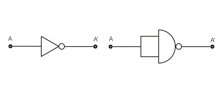 This is the circuit diagram of a NAND gate used to make work like a NOT gate, the original logic gate diagram of NOT gate is given besides the circuit diagram below.


0 Comments
If you have any doubts, please let me know