
Aim :- To Construct And Test A Half-Wave Rectifier (HWR)
And A Full-Wave Bridge Rectifier (FWR).
🛠️ Components and Equipment
AC Power Source: A function generator (recommended) or a step-down transformer (e.g., 220V/12V or 110V/6V, depending on your region and components) to provide a low-voltage AC input.
Diodes: General-purpose rectifier diodes (e.g., 1N4001 or similar).
HWR: 1 Diode
FWR (Bridge): 4 Diodes
Load Resistor ($\mathbf{R_L}$): A carbon film resistor (e.g., 1 k$\Omega$ or similar).
Capacitor (for filtering): An electrolytic capacitor (e.g., 100 $\mu$F to 1000 $\mu$F) to observe the smoothing effect.
Measurement Tools:
Oscilloscope (CRO): Essential for viewing the AC input and pulsating DC output waveforms.
Digital Multimeter (DMM): For measuring AC RMS voltage and DC average voltage.
Other: Breadboard, connecting wires.
1. Half-Wave Rectifier (HWR) Experiment

A. Construction 🏗️
Circuit Diagram: The circuit is a series connection of the AC source, a diode ($\mathbf{D_1}$), and the load resistor ($\mathbf{R_L}$).
Steps:
Connect the AC source to the anode of the diode ($\mathbf{D_1}$).
Connect the cathode of the diode to one end of the load resistor ($\mathbf{R_L}$). (The cathode is usually marked with a band/line).
Connect the other end of $\mathbf{R_L}$ back to the other terminal of the AC source to complete the loop.
B. Testing (No Filter) 📉
Input Waveform: Connect Channel 1 of the oscilloscope across the AC source terminals. Observe and record the waveform (a sine wave) and its measurements (Peak Voltage (Vp,in) and Frequency (fin).
Output Waveform: Connect Channel 2 of the oscilloscope across the load resistor (RL).
Observation: Observe and record the output waveform. You should see only the positive half-cycles of the input sine wave, with a slight drop in peak voltage due to the diode's forward voltage drop (Vp,out approx Vp,in} - 0.7V for a silicon diode). The negative half-cycles should be clipped off (zero output).
Measurement: Use the DMM to measure the AC RMS voltage (Vrms,out) and DC Average voltage (Vavg,out) across RL.
C. Testing with Capacitor Filter 📈
Add Filter: Connect the electrolytic capacitor (C) in parallel with the load resistor (RL). Ensure the correct polarity (negative side to ground/negative line of the rectifier output).
Observation: Observe the output waveform across RL on the oscilloscope. The pulsating DC will now be smoothed out, resembling a higher DC level with a small ripple voltage.
Measurement: Measure and record the new DC Average voltage (Vavg,out,filtered) and the Peak-to-Peak Ripple Voltage (Vr,p-p) from the oscilloscope.
2. Full-Wave Bridge Rectifier (FWR) Experiment

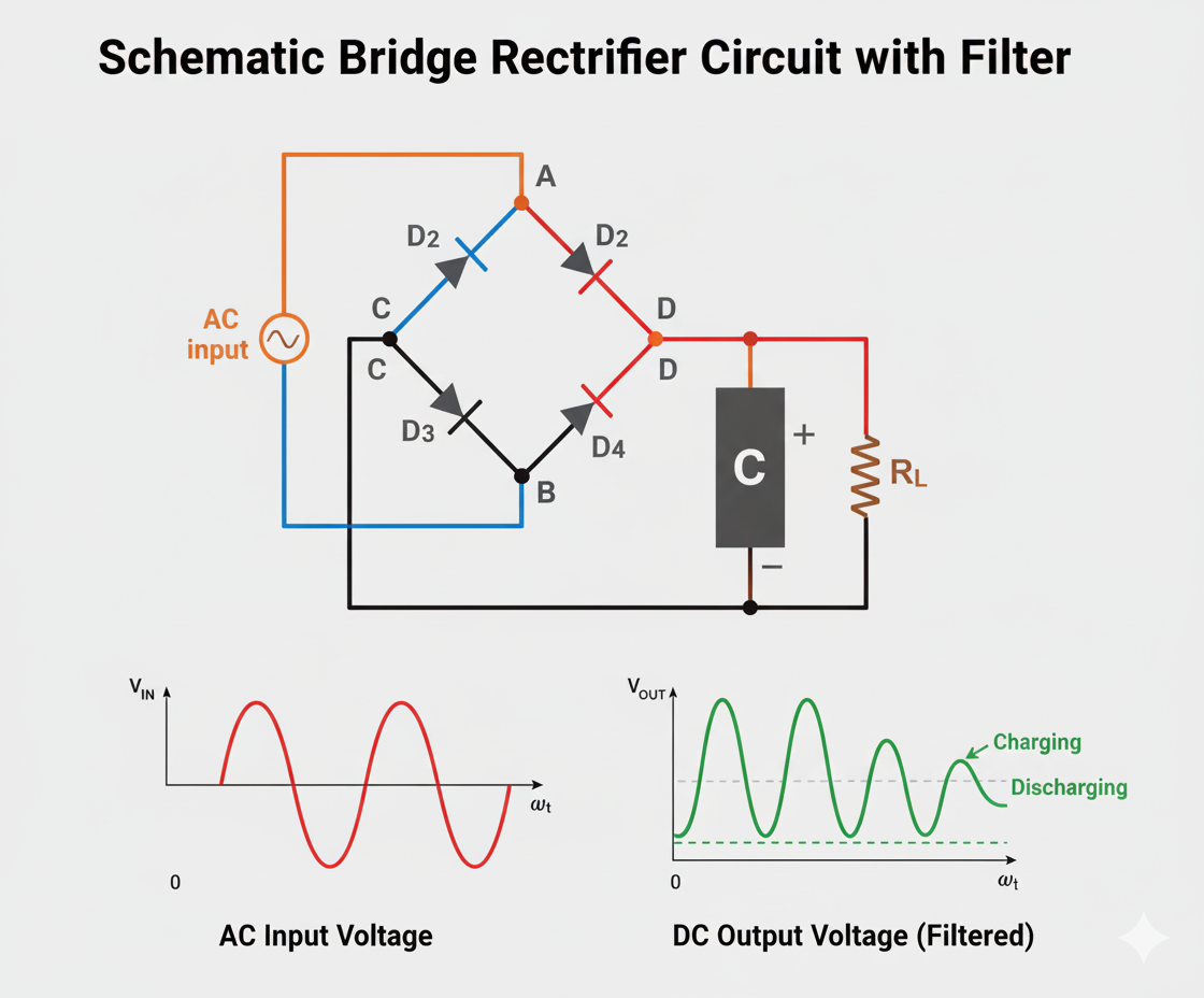
A. Construction 🏗️
Circuit Diagram: Connect the four diodes (D1, D2, D3, D4) in a bridge configuration.
Steps:
Connect the AC source to the two opposite nodes in the bridge structure (the junction of D1 cathode/D4 anode and the junction of D2 cathode/D3 anode).
The positive output (pulsating DC) is at the junction of the two diode cathodes (D1 and D3).
The negative output (ground reference) is at the junction of the two diode anodes (D2 and D4).
Connect the load resistor (RL) between the positive and negative output terminals.


 And A Full-Wave Bridge Rectifier (FWR).)
0 Comments
If you have any doubts, please let me know