Friday 20 October 2023

Practical - 7 :- Measure the voltages of the given cells/battery using analog/digital multimeter

Measure the voltages of the given cells/battery using analog/digital multimeter 

Objectives: At the end of this exercise you shall be able to

  • Measure the voltage of given cell/battery using analog multimeter 
  • Measure the voltage of given cell/battery using digital multimeter.

Requirements Tools/Equipment's/Instruments

  • Digital multi meter with probes - 1 No
  • Analog multi meter with probes- 1 No

Materials/Components

  • Lead acid battery 6V/12V any AH rating  - 1 No
  • 1.5V/3V/9V battery -1 No each
Digital-and-Analog-Multimeter-Parts

PROCEDURE 

TASK 1 : Measurement of cell/battery voltage using analog multimeter

  1. Observe the front panel and insert the black colour probe “COM” socket of analog multimeter and insert the red colour probe into the V mA : socket as shown in Fig 1
    Multimeter ports
  2. Set the range selector knob of multimeter to DCV, as shown in Fig 2. 
    Multimeter functions switch
  3. Set the voltage range nearest to the cell / battery voltage as shown in Fig 3.
    Measuring resistance with multimeter probes
  4. Pick the 9V battery, place the black probe on the negative (-) terminal and red probe on the positive (+) terminal of the battery as shown in Fig 4.
  5. Check the Analog voltmeter reading as shown in Fig 5 and record the reading in Table 1. 6 Repeat step 4 and 5 for the remaining labelled cells/ battery. 7 Get the work checked by the Instructor

Experiment No. 6 Resistor Color Code and Measurement of Resistance

 Experiment No. 6 Resistor Color Code and Measurement of Resistance

 1. Introduction

 Objective: The aim of this experiment is to learn how to use the multimeter and how to calculate the                       value of the resistor.

 Components:

  •  Set of Resistors;
  • Multimeter.

1.3 Theory

1.3.1. Resistor: A passive electrical component with two terminals that are used for either limiting or regulating the flow of electric current in electrical circuits. The main purpose of resistor is to reduce the current flow and to lower the voltage in any particular portion of the circuit. It is made of copper wires which are coiled around a ceramic rod and the outer part of the resistor is coated with an insulating paint. 


Tolerance: Tolerance indicates how much the measured value of its actual resistance is different from its theoretical value, and it is calculated using percentages.

Resistor Color Code Chart

The chart below shows how to determine the resistance and tolerance for resistors. The table can also be used to specify the color of the bands when the values are known. An automatic resistor calculator can be used to quickly find the resistor values.

resistor color code chart

How to Read Resistor Colour Code?


four band resistor color code


  1. To read them, hold the resistor such that the tolerance band is on your right. The tolerance band is usually gold or silver in colour and is placed a little further away from the other bands.
  2.  Starting from your left, note down all the colours of the bands and write them down in sequence. 
  3.  Next, use the table given below to see which digits they represent.


    five band resistor color code

  4. The band just next to the tolerance band is the multiplier band. So if the colour of this band is Red (representing 2), the value given is 102 .

Experiment - 09 :- Desoldering Components from PCB using Desoldering pump

Objectives : At the end of this exercise you shall be able to 

• desoldering components from PCB using desoldering pump 

• desoldering component using desoldering wick. Requirements Tools/Equipments/Instruments 

• Trainees tool kit 

- 1 Set • Soldering iron, 25W 

-1 No • Desoldering pump (plunger type)

 - 1 No • Heat sink plier - 1 No

 Materials/Components 

• Desoldering wick - as reqd

 • Cleaning solution (IPA) - as reqd

 • Flux - as reqd

 • Cleaning Brush - 1 No

 • Safety goggles

 - 1 No • Crocodile clip

 - 1 No • Assembled PCB board for Desoldering work - as reqd

DESOLDERING

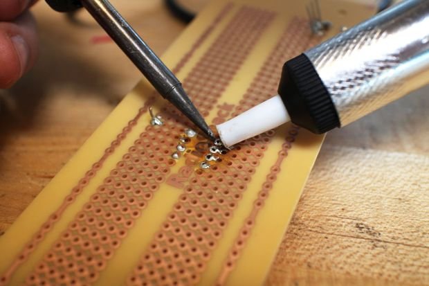
From using desoldering irons to sketchily knocking breadboard components off on the side of a table, there are tons of ways to remove components from a circuit board. Desoldering is an important skill to learn once you've gotten the hang of soldering, because messing up a soldering job isn't improbable.

  • This process is the removal of solder and components from a circuit board for troubleshooting, repair, replacement, and salvage.
  • It is the reverse process of soldering.
  • It is a process of removal of solder and components mounted on circuit boards.
  • The soldered joint is removed by the process of desoldering. For this purpose a small vacuum pump is used to remove solder from the plated through holes.
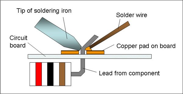
  • The lead over which the desoldering tip was placed is moved in a circular motion for rounded leads and back and forth for flat leads

Desoldering Basics

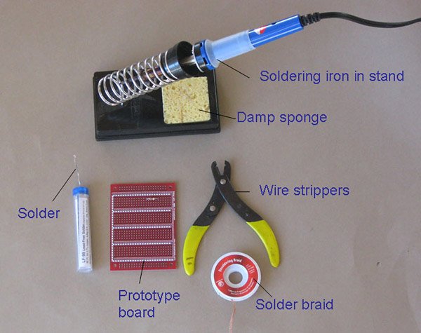
Materials Needed for Desoldering

a. Solder Sucker/ Desoldering Pump


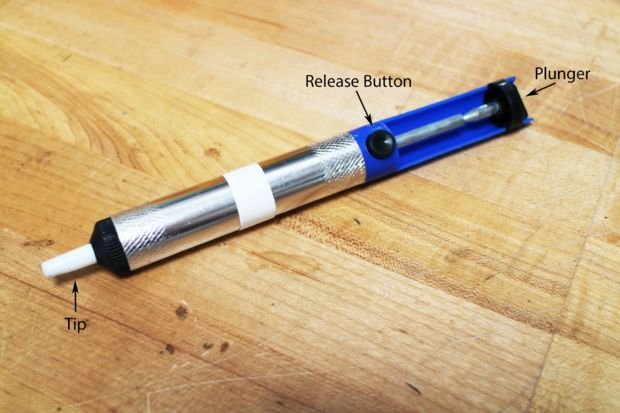
The most commonly used and convenient equipment needed for desoldering is the desoldering pump. A good manual solder sucker like this one works pretty well for selectively removing through holes parts from a PCB. Cheaper and smaller units do not work as well. They're marketed as compact but they don't works as well due to the limited stroke length and smaller cylinders.

Desoldering Process

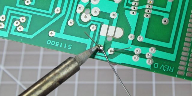
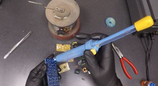
One of the nicest ways to desolder a component involves using a desoldering pump. A desoldering pump is essentially a small, high pressure vacuum. After heating up the solder, you can use the desoldering pump to suck the solder up and out of the way. Here are the basic steps for using a hand-powered desoldering pump:

1. Heat up the solder you want to remove with a soldering iron (some desoldering pumps also come with attached irons).
2. Press down on the plunger (If your pump has a bulb, just squeeze the bulb).
3. Once the solder is molten, place the tip of the desoldering pump against the solder that you want to remove.

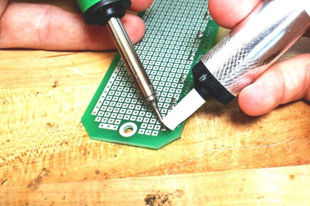
4. Release the plunger or bulb. Some desoldering pumps have a release button so that you don't have to hold it the whole time.

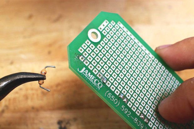
5. Remove free component.
6. Repeat steps 1-4 to remove any excess solder.
7. Dispose of the solder inside the pump by repeatedly pressing down and releasing the plunger.

Experiment - 08 :- Soldering the IC base on PCB

 Practice soldering IC bases on PCBs 

Objectives: At the end of this exercise you shall be able to 

  • soldering IC bases on PCB
  • inspect the soldered joints of IC bases on the PCB.


SOLDERING


Soldering is a skill anyone working or experimenting in electronics needs to know. Proper soldering takes practice, patience, and persistence. Solder is a metallic “glue” that holds the parts together and forms a connection that allows electrical current to flow.

  • Soldering is a process in which two or more metal items are joined together by melting and then flowing a filler metal into the joint—the filler metal having a relatively low melting point.
  • Soldering is used to form a permanent connection between electronic components.
  • The metal to be soldered is heated with a soldering iron and then solder is melted into the connection.
    Only the solder melts, not the parts that are being soldered.

Soldering Basics

Materials Needed for Soldering

A. Soldering Iron

  • A soldering iron is used to heat the connections to be soldered.
  • For electronic circuits, you should use a 25- to 40-watt (W) soldering iron.
  • Higher wattage soldering irons are not necessarily hotter; they are just able to heat larger components.
  • A 40-W soldering iron makes joints faster than a 25-W soldering iron does.

B. Solder/Soldering Lead ( Rosin Core Solder)

  • Solder has a lower melting point than the metals that are being connected do. The solder melts when it is heated by the soldering iron, but the metals being joined will not melt.
  • The rosin core acts as a flux. It prevents oxidation of the metals that are being connected, and enhances the ability of the solder to "wet" the surfaces that are being joined.
  • Solder that is used to join copper pipes has an acid core, which is appropriate for pipes, but will corrode electronic connections. Use solder that has a rosin core.
  • For most electronics work, a solder with a diameter of 0.75 millimeters (mm) to 1.0 mm is best.
  • Thicker solder might make soldering small joints difficult and also increases the chances of creating solder bridges between copper pads that are not meant to be connected.
  • An alloy of 60/40 (60% tin, 40% lead) is used for most electronics work, but lead-free solders are available as well.

C. Soldering Stand

  • There are a variety of stands available. It is important to always keep the hot iron in its stand when not in use.

D. Sponge

  • The damp sponge is used to clean the tip of the iron.

E. Solder Braid

  • This is used to remove solder.
  • To use the braid, place it over the solder to be removed and heat it from above with the iron. The solder will flow into the braid.
  • Solder braid is used to extract an electronic component that is soldered onto a board.
  • It is also used to reduce the amount of solder on a connection.

F. Prototype Board

  • A prototype board is used to assemble the circuit.
  • Prototype boards have copper tracks or pads for connecting components.

G. Steel wool or Fine Sandpaper

  • This is used to clean connections prior to soldering.
  • Solder will not flow over a dirty connection.

Soldering Process

1. Solder needs a clean surface on which to adhere.

  • Buff the copper foil of a PC board with steel wool before soldering.
  • Remove any oil, paint, wax, etc. with a solvent, steel wool, or fine sandpaper.
2. To solder, heat the connection with the tip of the soldering iron for a few seconds, then apply the solder.
  • Heat the connection, not the solder.
  • Hold the soldering iron like a pen, near the base of the handle.
  • Both parts that are being soldered have to be hot to form a good connection.
3. Keep the soldering tip on the connection as the solder is applied.
  • Solder will flow into and around well-heated connections.
  • Use just enough solder to form a strong connection.
4. Remove the tip from the connection as soon as the solder has flowed where you want it to be. Remove the solder, then the iron.
5. Don't move the connection while the solder is cooling.
6. Don't overheat the connection, as this might damage the electrical component you are soldering.
  • Transistors and some other components can be damaged by heat when soldering. A crocodile clip can be used as a heat sink to protect these components.

7. Soldering a connection should take just a few seconds.
8. Inspect the joint closely. It should look shiny.
  • If you are soldering a wire (called the lead) onto a PC board (on the track), it should have a volcano shape.
  • If the connection looks bad, reheat it and try again.

9. Wipe the tip of the iron on a damp sponge to clean it. The tip should now be shiny.
10. Unplug the soldering iron when it is not in use.

Experiment - 11 :- Practice on measurement of parameters in combinational electrical circuit by applying Ohm’s Law for different resistor values and voltage sources

Material required :

A resistor of about 5 Ω, an ammeter ( 0 - 3 A), a voltmeter (0 - 10 V), four dry cells of 1.5 V each with a cell holder (or a battery eliminator), a plug key, connecting wires, and a piece of sand paper.

Precautions :

  • All the electrical connections must be neat and tight.
  • Voltmeter and Ammeter must be of proper range.
  • The key should be inserted only while taking readings.

Circuit Diagram:

 Procedure :

  1. Draw the circuit diagram as shown above.
  2. Arrange the apparatus as per the circuit diagram.
  3. Clean the ends of the connecting wires with sand paper and make them shiny.
  4. Make the connections as per circuit diagram. All connections must be neat and tight. Take care to connect the ammeter and voltmeter with their correct polarity. (+ve to +ve and -ve to -ve).
  5. Determine the zero error and least count of the ammeter and voltmeter and record them.
  6. Adjust the rheostat to pass a low current.
  7. Insert the key K and slide the rheostat contact to see whether the ammeter and voltmeter are showing deflections properly.
  8. Adjust the rheostat to get a small deflection in ammeter and voltmeter.
  9. Record the readings of the ammeter and voltmeter.
  10. Take atleast six sets of readings by adjusting the rheostat gradually.
  11. Plot a graph with V along x-axis and I along y-axis.
  12. The graph will be a straight line which verifies Ohm's law.
  13. Determine the slope of the V-I graph. The reciprocal of the slope gives resistance of the wire.

Observations:

  • Range of the given ammeter=.................... A.
  • Least count of the given ammeter = ..................... A.
  • Range of the given voltmeter = .....................V.
  • Least count of the given voltmeter = .....................V.
  • Mean value of V/I from observations, R = .......... Ω.

Observation from graph:

  • Slope of I vs V graph = ...........
  • R from graph = 1/ slope = .............. Ω.

Observation table:


Thursday 19 October 2023

Experiment No - 10 Measurement of current and voltage in electrical circuits to Kirchhoff’s Law verify

Measurement of current and voltage in electrical circuits to Kirchhoff’s Law verify

Objectives       :  At the end of this exercise you shall be able to

• verify the Kirchhoff's Current Law with three branch circuit

• verify the Kirchhoff's Voltage Law with one voltage source.


Requirements

Materials/Components

  • SPST Toggle Switch/1A - 1 No
  • Resistor, 1k:/1W - 3 Nos
  • Resistor, 2.2k:1W - 1 No
  • Resistor, 3.3k:/1W - 1 No
  • Rosin cored solder - 1 m
  • Soldering flux - 1 Box
  • Hook-up wires - 2 m
  • Patch Cords - 10 Nos
  • Lug Board - 1 No

Tools/Equipment/Instruments

  • Trainees Tool Kit - 1 Set
  • Soldering Iron, 230V/25 watts - 1 No
  • Milli-Ammeter, 0-10m.A, DC - 3 Nos
  • Milli-Ammeter, 0-5m.A, DC - 1 No
  • Multi meter with probes - 1 No
  • Regulated DC power supply 0-30V/1A - 1 No

PROCEDURE

TASK 1: Verification of Kirchhoff's Current Law

  1. Check physical and electrical condition of the given ammeter, meter prods, patch cords, toggle switch soldered on the lug board.
  2. Make the connections on the Lug board as per the circuit diagram. (Fig 1)
  3. With the SPST in OFF position, set the output of Power Supply to 12 volts. 

  4. Switch ON the SPST switch. Measure and record currents, IT, IB1, IB2, and IB3 in Table-1.
  5. Switch OFF SPST and PSU.
  6. Write Kirchhoff's current equations at Nodes P and Q. Verify the equation using measured current values.
  7. Get the work checked by the Instructor.

TASK 2: Verification of Kirchhoff's voltage  Law

  1. Check physical and electrical condition of the given meter probes, patch cords, toggle switch soldered on the lug board. 
  2. Measure and record the values of Resistor R1, R2 and R3 in the Table.
  3. Make the connection on the Lug board as per the circuit diagram. (Fig 2)
  4. With the SPST in OFF position, set the output of Power Supply to 12 volts. 

  5. Mark the polarity of the voltage drops across resistors R1, R2 and R3.
  6. Switch ON the SPST switch.
  7. Following the voltage polarities marked across the resistors, measure and record the voltage drop across R1, R2 and R3 in Table.
  8. Switch OFF SPST and Regulated power supply.
  9. Write Kirchhoff's loop equations for the closed paths a-c-d-b-a, a-e-f-b-a and c-e-f-d-a. Substitute the voltage readings recorded in Table in the equations for verification.
  10. Verify the equation using measured voltage values.
  11. Get the work checked by the Instructor.
Loop:- a-c-d-b-a:

                       +V1 +V2 - VT = 0

                       +V1 +V2 = VT

           Loop:- a-c-e-f-d-b-a: 

                        +V1 +V3 - VT = 0 

                        +V1 +V3 = VT

Loop:- c-e-f-d-e:

                       +V3 - V2 = 0 V3 = V2


Popular Posts