
SMPS is nothing but an electronic circuit
which is used in most of the electronic devices to provide their required
voltage and current. We know that electronic circuits and devices are very
sensitive. Most of the electronic devices work on DC power supply. An
electronic circuit may contain different components and they required different
voltage and current. So the main purpose of the use of SMPS is to provide the
required voltage and current for each component.
SMPS is used in computer. So there are many components
and circuits inside the computer. All of them does not take the same voltage
and current. In this case, the SMPS provides different voltage and current to
different components and circuits according to their requirement.
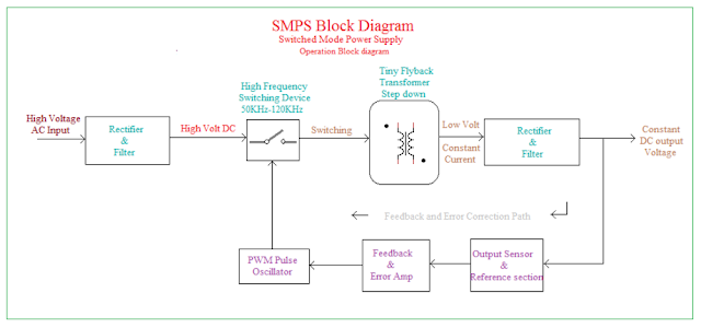
Switched Mode Power Supply Working Principle
- According to the above block diagram, the working principle is explained below.
- The first block is the Bridge rectifier circuit. So the input high voltage AC supply(230V) is given to the rectifier and it converted into high voltage DC(230V).
- Then the unfiltered DC is filtered by the filter circuit.
- Then the high voltage DC is converted into very high-frequency square wave AC. Here the high-frequency switch is used to convert DC to AC. The switch is controlled by the feedback and control circuit.
- The high-frequency AC is step down into low voltage( maybe 12V, 6V, etc) by a fly back high-frequency transformer.
- Then again a rectifier circuit is used to convert the low voltage AC to DC.
- A filter circuit is used to filter the DC.
- The feedback path and control circuits are used to control the output DC supply. Mainly the Pulse Width Modulation Circuit is used for the control circuit.


0 Comments
If you have any doubts, please let me know