
Counters
The
counter is one of the widest applications of the flip flop. Based on the clock
pulse, the output of the counter contains a predefined state. The number of the
pulse can be counted using the output of the counter.
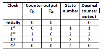
Truth Table
There
are the following types of counters:
- Asynchronous Counters
- Synchronous Counters
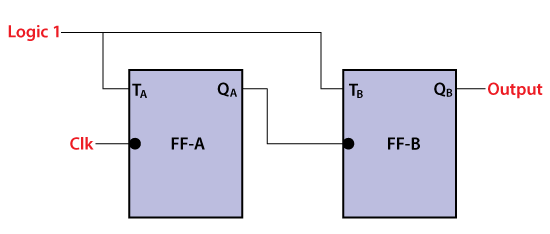
Asynchronous or ripple counters
The Asynchronous
counter is also known as the ripple counter. Below is a
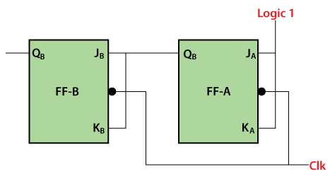
diagram of the 2-bit Asynchronous counter in which we used two
T flip-flops. Apart from the T flip flop, we can also use the JK flip flop by
setting both of the inputs to 1 permanently. The external clock pass to the
clock input of the first flip flop, i.e., FF-A and its output, i.e., is passed
to clock input of the next flip flop, i.e., FF-B.
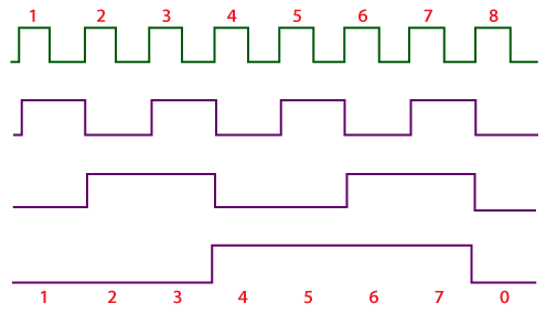
Block Diagram Signal Diagram
- Condition 1: When both the flip flops are in reset condition.
Operation: The outputs of both flip flops, i.e., QA QB, will be 0. - Condition 2: When the first negative clock edge passes.
Operation: The first flip flop will toggle, and the output of this flip flop will change from 0 to 1. The output of this flip flop will be taken by the clock input of the next flip flop. This output will be taken as a positive edge clock by the second flip flop. This input will not change the second flip flop's output state because it is the negative edge triggered flip flop.
So, QA = 1 and QB = 0 - Condition 3: When the second negative clock edge is applied.
Operation: The first flip flop will toggle again, and the output of this flip flop will change from 1 to 0. This output will be taken as a negative edge clock by the second flip flop. This input will change the second flip flop's output state because it is the negative edge triggered flip flop.
So, QA = 0 and QB = 1. - Condition 4: When the third negative clock edge is applied.
Operation: The first flip flop will toggle again, and the output of this flip flop will change from 0 to 1. This output will be taken as a positive edge clock by the second flip flop. This input will not change the second flip flop's output state because it is the negative edge triggered flip flop.
So, QA = 1 and QB = 1 - Condition 5: When the fourth negative clock edge is applied.
Operation: The first flip flop will toggle again, and the output of this flip flop will change from 1 to 0. This output will be taken as a negative edge clock by the second flip flop. This input will change the output state of the second flip flop.
So, QA = 0 and QB = 0
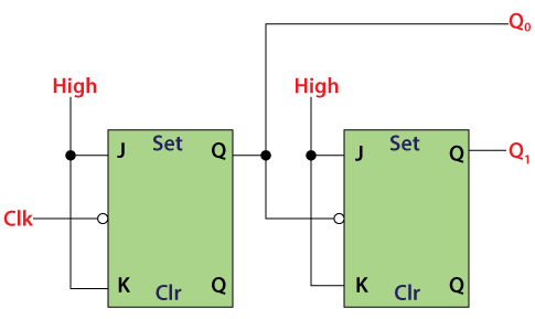
Synchronous counters
In the Asynchronous
counter, the present counter's output passes to the input of the next
counter. So, the counters are connected like a chain. The drawback of this
system is that it creates the counting delay, and the propagation delay also
occurs during the counting stage. The synchronous counter is
designed to remove this drawback.
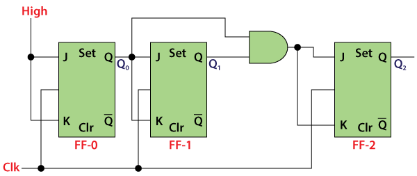
In the synchronous counter, the same clock pulse is passed to the clock input of all the flip flops. The clock signals produced by all the flip flops are the same as each other. Below is the diagram of a 2-bit synchronous counter in which the inputs of the first flip flop, i.e., FF-A, are set to 1. So, the first flip flop will work as a toggle flip-flop. The output of the first flip flop is passed to both the inputs of the next JK flip flop.
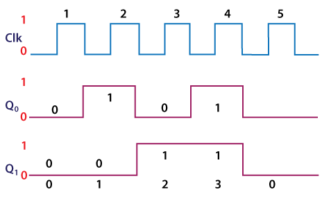
Logical Diagram Signal Diagram
Logical Diagram Signal Diagram
Operation
- Condition 1: When both the flip flops are in reset condition.
Operation: The outputs of both flip flops, i.e., QA QB, will be 0.
So, QA = 0 and QB = 0 - Condition 2: When the first negative clock edge passes.
Operation: The first flip flop will be toggled, and the output of this flip flop will be changed from 0 to 1. When the first negative clock edge is passed, the output of the first flip flop will be 0. The clock input of the first flip flop and both of its inputs will set to 0. In this way, the state of the second flip flop will remain the same.
So, QA = 1 and QB = 0 - Condition 2: When the second negative clock edge is passed.
Operation: The first flip flop will be toggled again, and the output of this flip flop will be changed from 1 to 0. When the second negative clock edge is passed, the output of the first flip flop will be 1. The clock input of the first flip flop and both of its inputs will set to 1. In this way, the state of the second flip flop will change from 0 to 1.
So, QA = 0 and QB = 1 - Condition 2: When the third negative clock edge passes.
Operation: The first flip flop will toggle from 0 to 1, but at this instance, both the inputs and the clock input set to 0. Hence, the outputs will remain the same as before.
So, QA = 1 and QB = 1


0 Comments
If you have any doubts, please let me know